Lackawanna Railroad Concrete
Tower in HO model scale
I have been working on and off on my model railroad, the New York,
Erie & Western, for something like 25 years. It is a
freelanced version of the Erie Lackawanna that combines all of the
Erie Lackawanna era into one era. The layout features more
locomotives much more rolling stock than I can ever fit onto the
layout. I painted most of the of the engines myself and
fitted the fleet with DCC decoders and use an NCE DCC system to
run the show.
I started collecting rolling stock and painting the locomotive
fleet before I began work on the layout. My former home was not
suitable for a model railroad that I hand in mind so I painted
engines and collected boxes and boxes of interesting rolling
stock. This brings us to the subject line of this little
story.
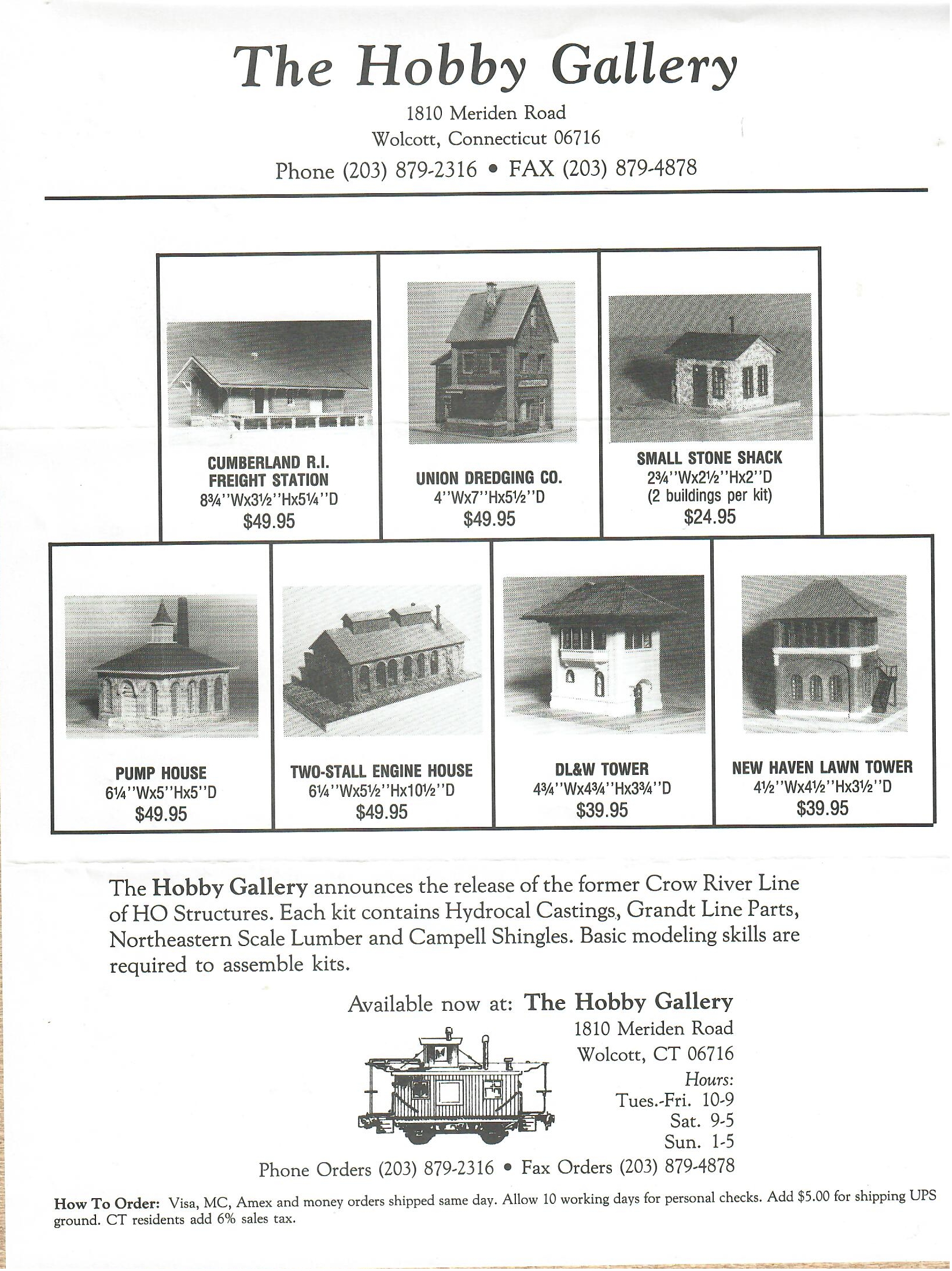
On 10-19-1992 I purchased two HO scale model kits of Lackawanna
Railroad concrete towers, for a grand total of $84.90. I
don't recall how I came across the advertisement for these but I
may have heard about the kits from an Erie Lackawanna Historical
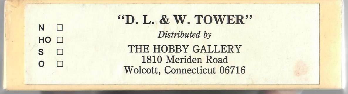
Society flyer. The kits were sold by The Hobby Gallery, 1810
Meridan Road, Wolcott, CT 06716. These kits are long out of
production and I have found very little information about the kits
or The Hobby Gallery. These kits may have been made by Crow
River Products, which I also have no information about. Here
are images of the box lid and box end label as well as a Hobby
Gallery advertisement.
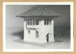
The kits were made of white plaster castings,
something that I have never had experienced working with
before. There were thick plaster castings of the roof and
walls and one small bay window part. The kit also contained
unpainted metal parts. There were also many unpainted metal
parts. Metal parts included all the windows,many metal roof
rafter tails, a metal side door roof overhang, metal bay window
parts and a metal chimney. And then there were many
unpainted wooded sticks, each stick was about a foot long and were
1/32x1/32 square or 1/16x1/16 square, and
3/64x3/32 square. The wooden sticks
were to be cut to make the spacers between the windows, somehow.
These kits were bewildering to me and thus sat untouched for
33+ years in their boxes.
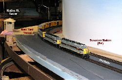
The The
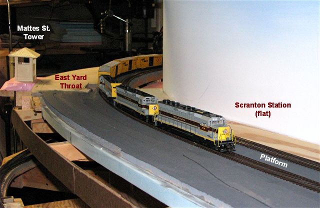
Hobby Gallery kits I purchased back in 1992 feature the smaller version of the Lackawanna Railroad concrete
towers that fit the type seen at Port Morris, NJ., Mattes Street
signal tower, Scranton, PA., 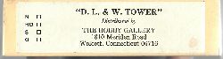 and
Greendell, NJ. The Lackawanna had some wider concrete towers which had and additional windows on
each side of the bay window.
and
Greendell, NJ. The Lackawanna had some wider concrete towers which had and additional windows on
each side of the bay window.
Loo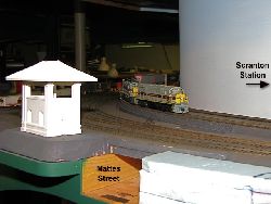 king
king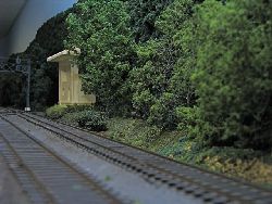
 abo
abo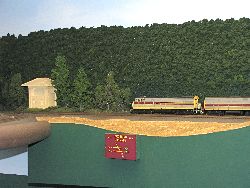 ut the
Internet in 2026 I find no references to the The Hobby Gallery Lackawanna tower models. But I did come across
images of what seems to be the plaster Hobby Gallery Lackawanna tower models
on Jeff Mutters's very impressive layout. The models appear in an unfinished plaster window-less state,
and judging on what an ordeal its was for me to put them together,
I am not surprised they are unfinished in the photos.
ut the
Internet in 2026 I find no references to the The Hobby Gallery Lackawanna tower models. But I did come across
images of what seems to be the plaster Hobby Gallery Lackawanna tower models
on Jeff Mutters's very impressive layout. The models appear in an unfinished plaster window-less state,
and judging on what an ordeal its was for me to put them together,
I am not surprised they are unfinished in the photos.
Here in 2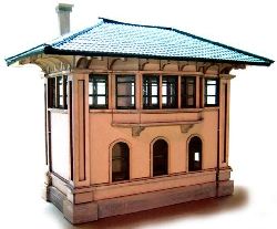 026, I see that another firm "The N Scale A
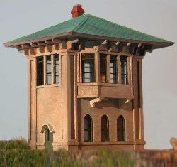 rchitect" offers nice looking model Lackawanna Railroad concrete
towers made from laser cut fiberboard. They offer both the
smaller and larger version of the Lackawanna Railroad concrete towers in laser cut fiberboard.
The model on the left is the larger wider version of a
Lackawanna Railroad concrete towers and is available in HO scale.
rchitect" offers nice looking model Lackawanna Railroad concrete
towers made from laser cut fiberboard. They offer both the
smaller and larger version of the Lackawanna Railroad concrete towers in laser cut fiberboard.
The model on the left is the larger wider version of a
Lackawanna Railroad concrete towers and is available in HO scale.
The image on the right is the smaller version of a Lackawanna Railroad concrete towers and is modeled in N scale.
I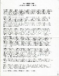
 n th
n th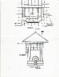 e
summer
e
summer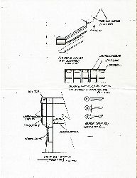 of 2026 I
got up enough nerve to try to tackle this
seemingly difficult plaster model kit. I started by a
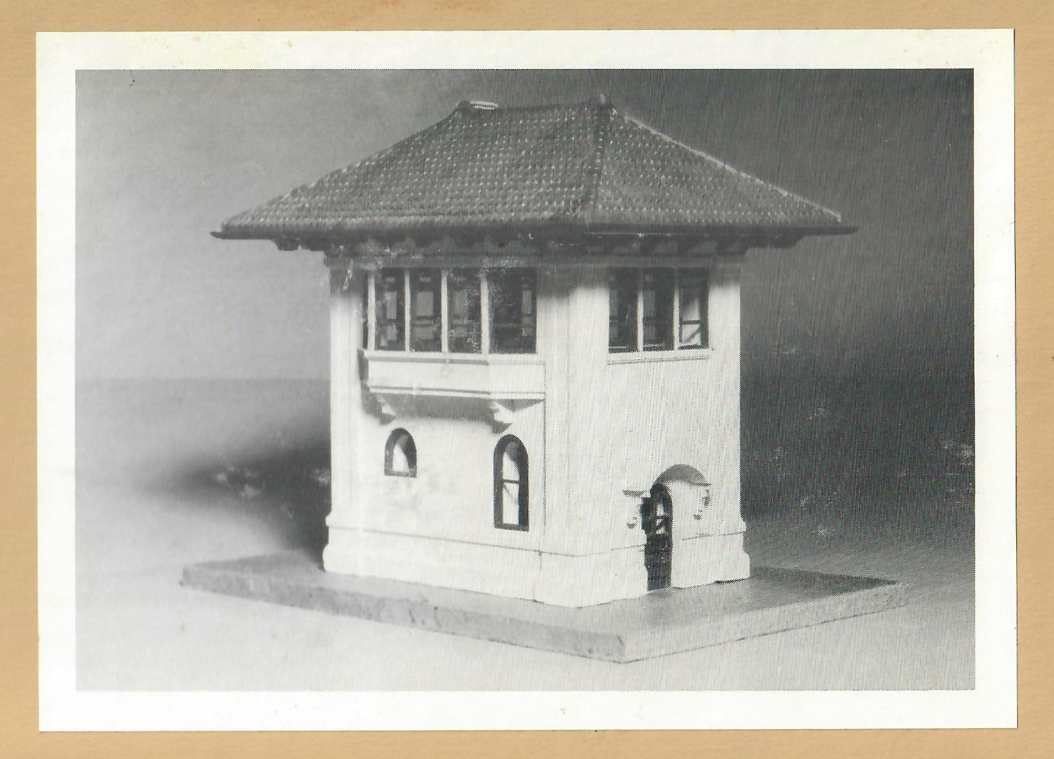
thorough study the images that came with
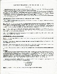
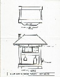
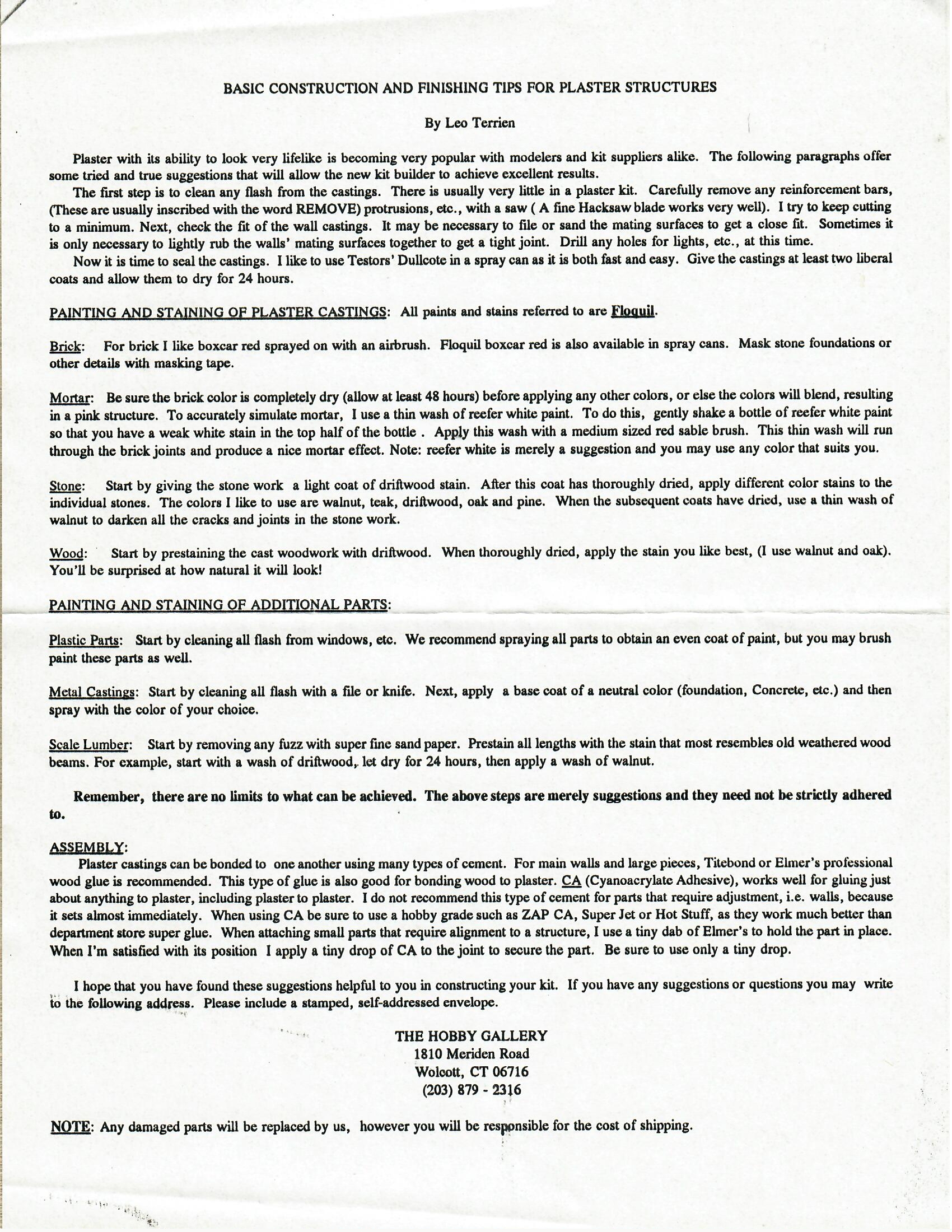
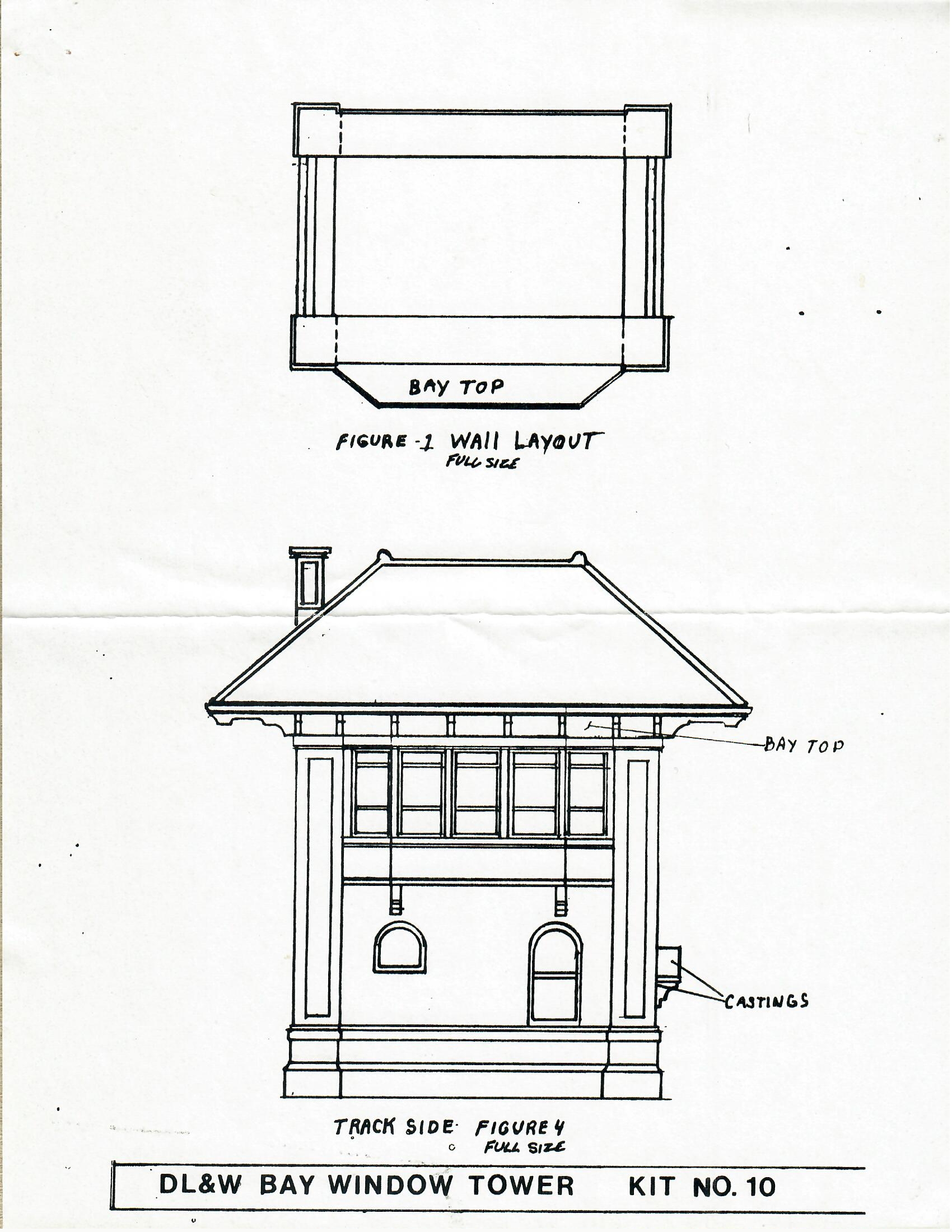
the structures. Here is the entirety of the paperwork that
came with the kits.
of 2026 I
got up enough nerve to try to tackle this
seemingly difficult plaster model kit. I started by a
thorough study the images that came with
the structures. Here is the entirety of the paperwork that
came with the kits.
The plaster parts
needed to be filed a bit to remove casting
irregularities. All the plaster parts got two coats of
Testors Spray Lacquer Clear Coat / dull coat spray.
All of the metal parts; the windows, the many roof rafter tails, the metal side
door roof overhang, and the metal portion of the bay window
needed filing to removed metal flash.
The pai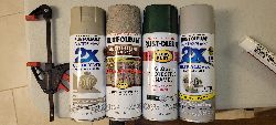
 nts that I
used were:
nts that I
used were:
1- Rust-oleum Painter's Touch, UltraCover Paint+Primer,
satin, in "Stone Gray". This was used as a base coat to
further seals the thirsty porous plaster.
2- Rust-oleum Painter's Touch, UltraCover Paint+Primer,
satin, in "Fossil" color. This was used for the walls, all
the wooden sticks, roof rafter tails,
and the big roof casting.
3- Rust-oleum Mutlicolor Textured "Desert Bisque".
This has a bumpy textured finish and mimics rough concrete in
the model. This was sprayed to the walls and then masked off so
a further application of "Fossil" could be applied.
4- Rust-oleum Gloss Protective Enamel, "Hunter
Green". This was used on the roof and windows.
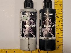
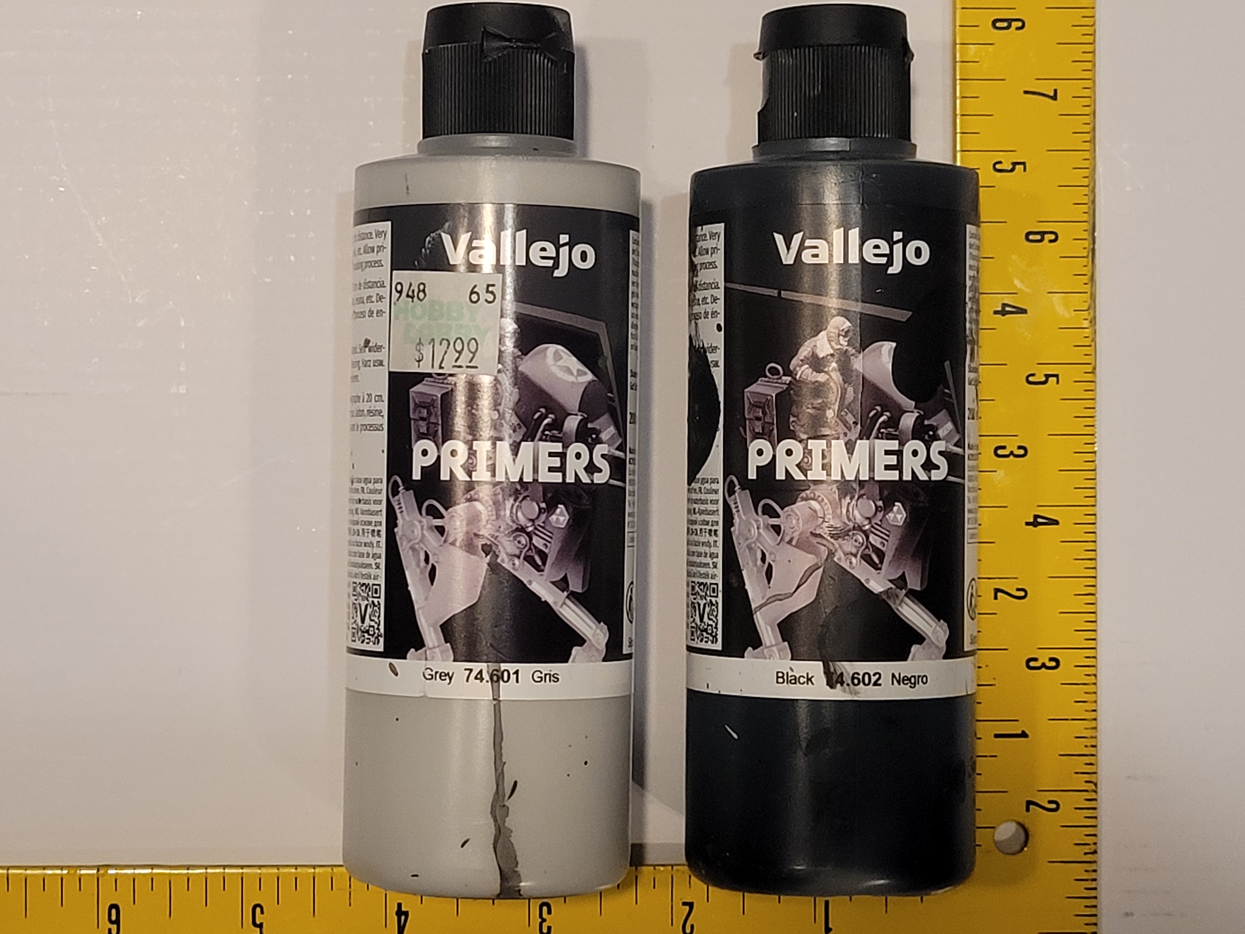
5- I also used a bit of Vallejo Surface Primer, Grey
Acrylic Primer and Black Acrylic Primer. This was applied
as a mixture diluted in alcohol to weather the roof of the
structure.
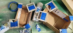
Here are the plaster wall panels and bay window parts after
being painted with Rust-oleum Mutlicolor
Textured "Desert Bisque" textured paint. Blue and
white masking tape has been applied to the areas where the "Desert
Bisque" paint is to be shielded from the next layer
of paint, which would be Rust-oleum Painter's
Touch, UltraCover Paint+Primer, satin, in
"Fossil".
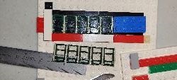
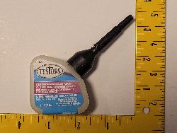
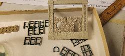
The Windows came as
individual metal castings which I painted Rust-oleum Gloss Protective
Enamel, "Hunter Green".
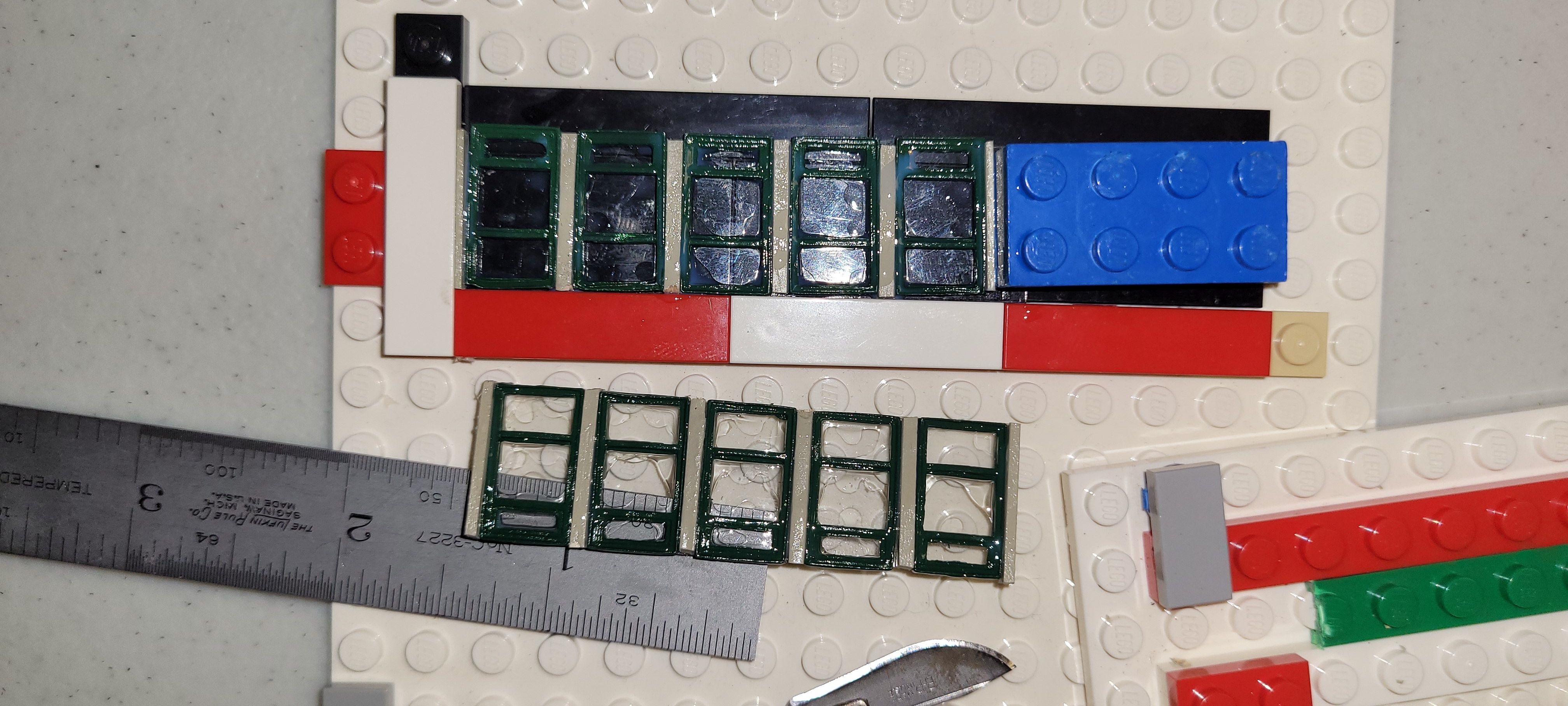
I assembled the multiple window assemblies using
a little right angle jig that I made out of some
Lego pieces. On the underneath the windows
I used a piece of clear plastic (from a grocery
store fresh lettuce packaging lid) that I cut
into a rectangles slightly larger in size than
the final window assembly would be. This
clear plastic would serve as window glazing and
the backbone structure of the window
assembly.
I then arranged the little "Fossil" colored wooden strips
and green windows in an alternating pattern on
top of the clear plastic sheet using the Lego
jig to help keep things lined up. Once I
was happy with how the windows and wooden strips
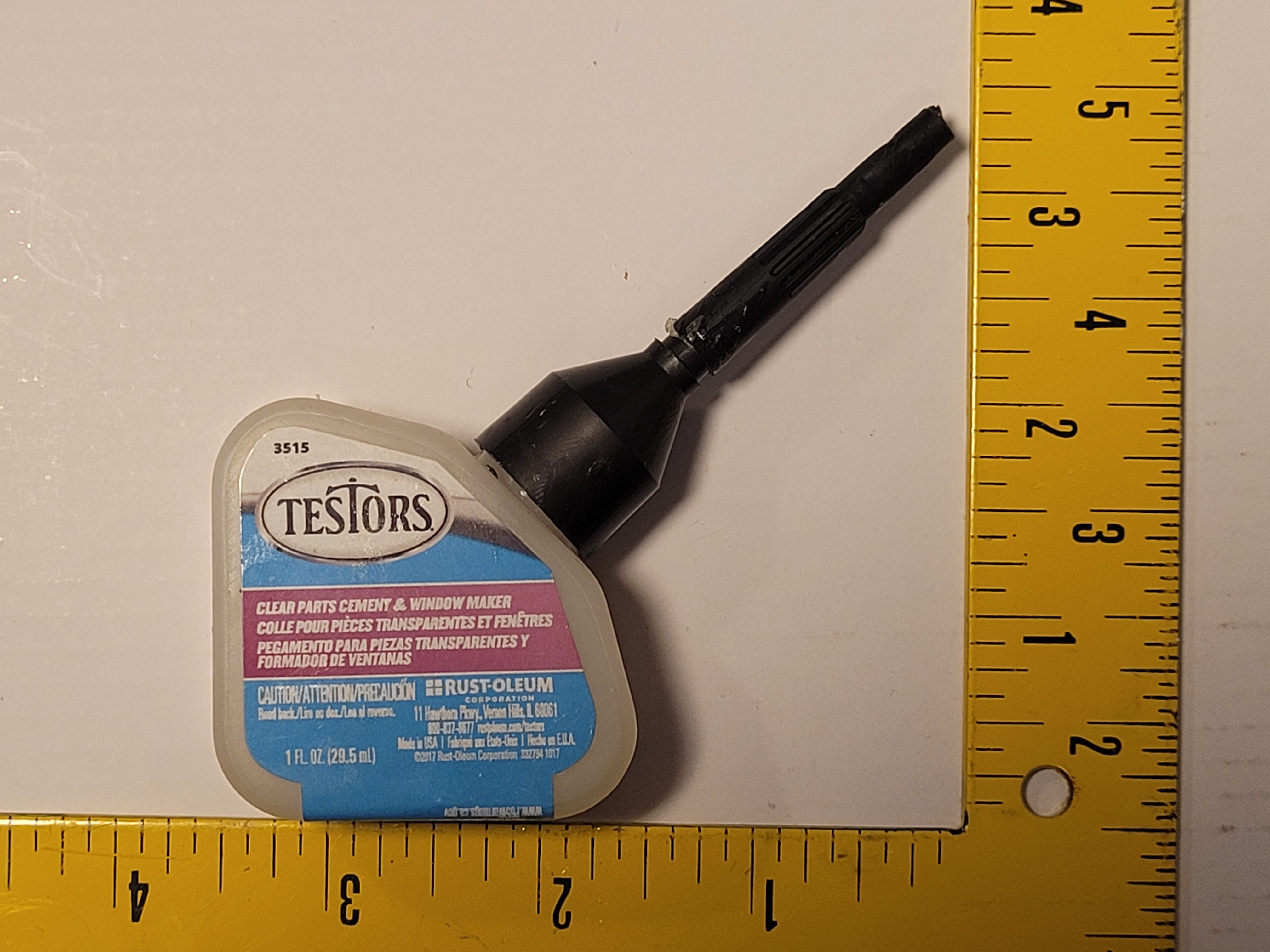
looked in the jig I added a bit of Testors Clear
Parts Cement & Window Makers to glue the
assembly together. After the glue had time
to set, I trimmed the excess clear plastic and
the result was a multiple pane window assembly
held together by the clear plastic window pane
sheet.
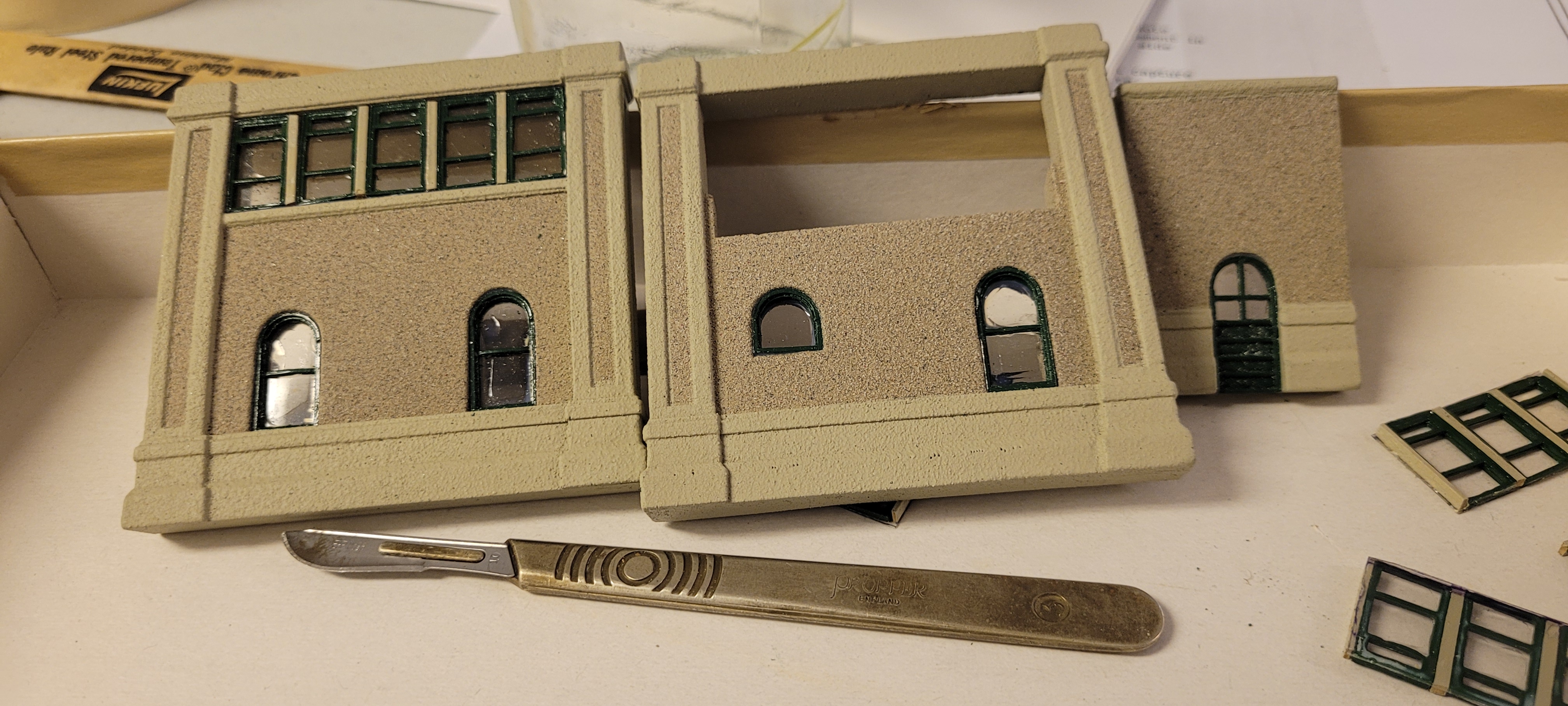
Then the window assemblies needed to be
installed into the plaster walls. This
again required filing and sanding of both the
plaster and the window assemblies. The
window assemblies fell apart on two occasions
that then required another trip to the Lego
glueing jig. The assemblies were glued
into the plaster openings with Testors
Clear Parts Cement &
Window Makers to glue.
At this point I did not
install the end windows nor
the bay windows. That
adventure would happen
later. But first, the
walls needed to be glued
together.
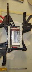
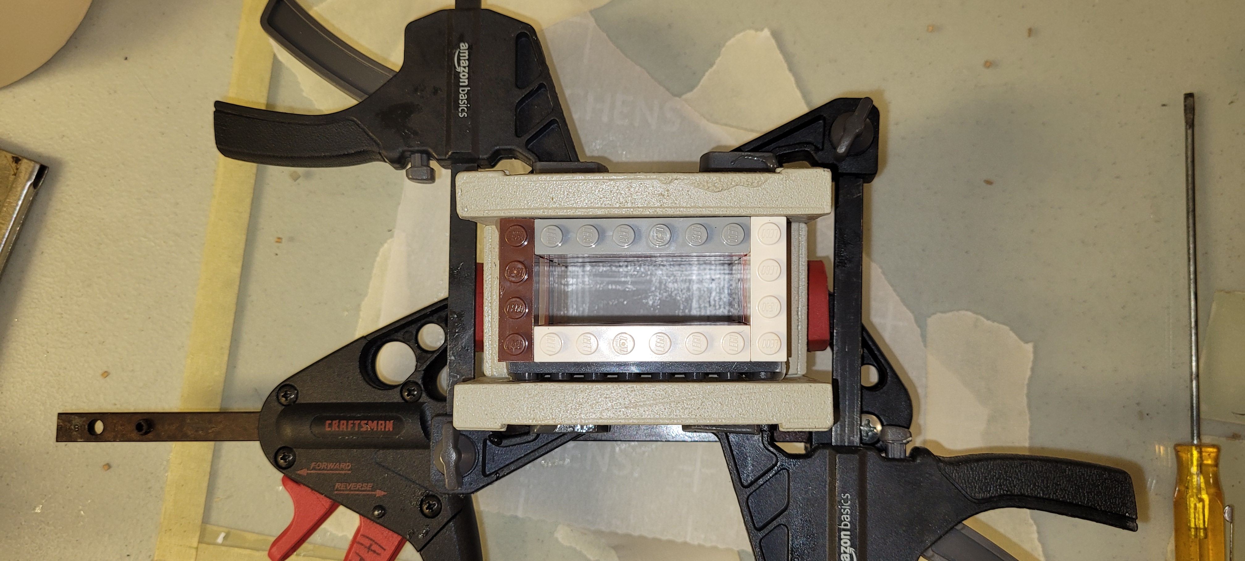
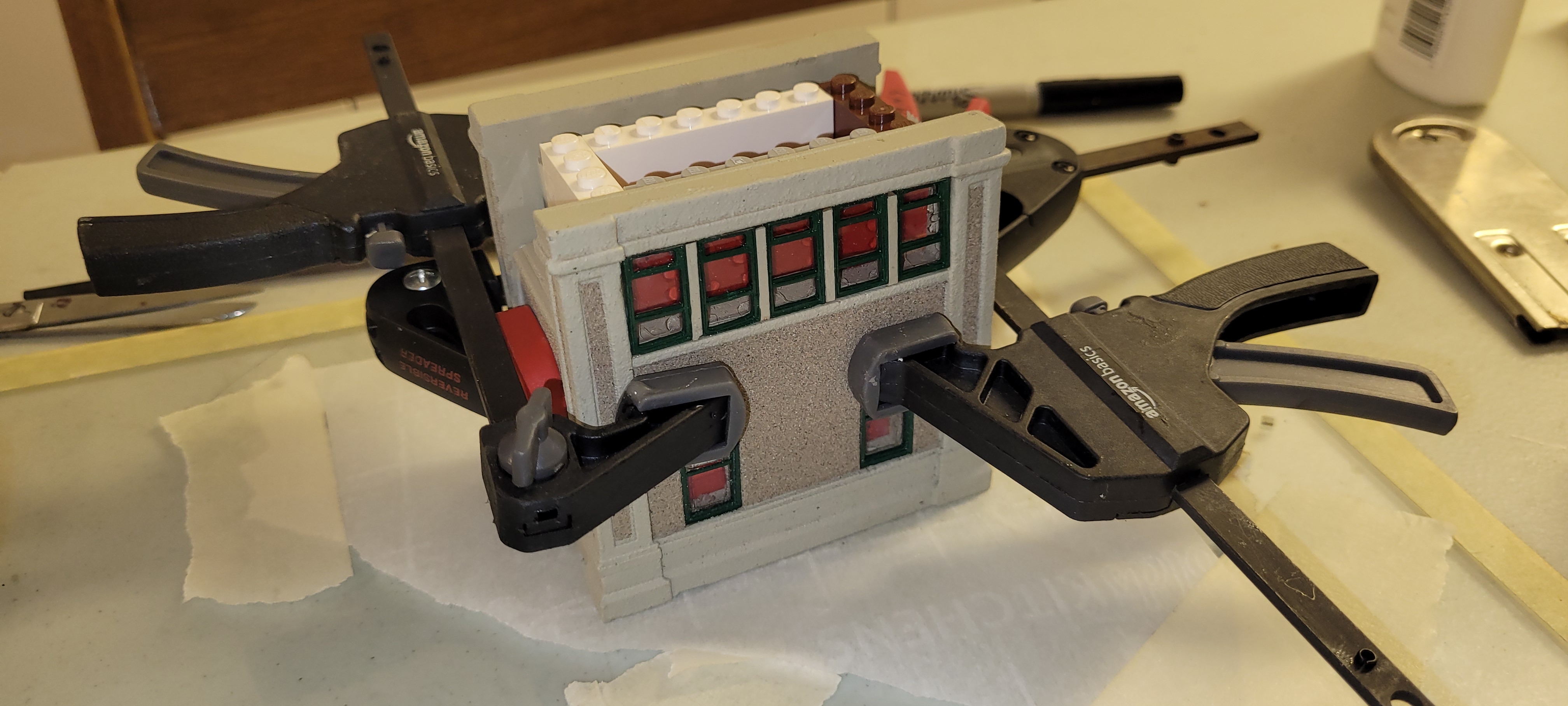
The walls nee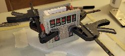 ded
to be glued with 90 degree
angles between them.
The plaster castings had no
reference points to do
so. So I made another
jig out of Lego. The
jig was wrapped in a bit of
tape to bring it up to the
right dimensions and greased
with plumbers lubricant so
the glue would not adhere to
the jig. I used plain
white Elmer's glue and
gently clamped the walls to
the jig. I was careful
to inset the side walls
1/32" which "defined the
corner columns" as stated in
the
instructions.
ded
to be glued with 90 degree
angles between them.
The plaster castings had no
reference points to do
so. So I made another
jig out of Lego. The
jig was wrapped in a bit of
tape to bring it up to the
right dimensions and greased
with plumbers lubricant so
the glue would not adhere to
the jig. I used plain
white Elmer's glue and
gently clamped the walls to
the jig. I was careful
to inset the side walls
1/32" which "defined the
corner columns" as stated in
the
instructions.
This Lego jig was made with
the inside hollow.
After the plaster set, I was
able to remove the Lego jig
by pulling the Lego pieces
inwards into the hollow
space. Had I not left
the Lego core hollow, I
doubt I would have been able
to remove the Lego jig from
the four walls of the
building.
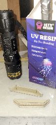
The building's bay window
assembly consists of an
upper trapezoidal plaster
casting that also
establishes the upper edge
of the bay windows.
The lower part is a trapezoidal
metal
casting along with three
metal wall pieces, one long
and the other two
short. This would
establish the lower edge of
the bay windows. Much
time was spent with a trial
and error dry fitting of
these pieces, filing where
necessary. The spacing
between the upper plaster trapezoidal
plaster
casting and
the lower
metal bay
window
assembly
needed to be
just right so
that the
actual window
assemblies
would fit.
Eventually,
when things looked as good
as they were going to get, I
glued the lower four metal
pieces together using UV
resin glue. This glue
is a sticky clear glue with
the consistency of
honey. When exposed to
ultraviolet lights using a
special UV flashlight, it
hardens in less than a
minute. This glue was
a game changer as it allowed
me to adjust fiddly parts
till they were just in the
right position and then I
would zap the area with the
ultraviolet
light and the
parts would
stay put.
The photo to
the left shows
two of the
lower metal
bay window
assemblies,
one is right
side up and
the other
upside
down.
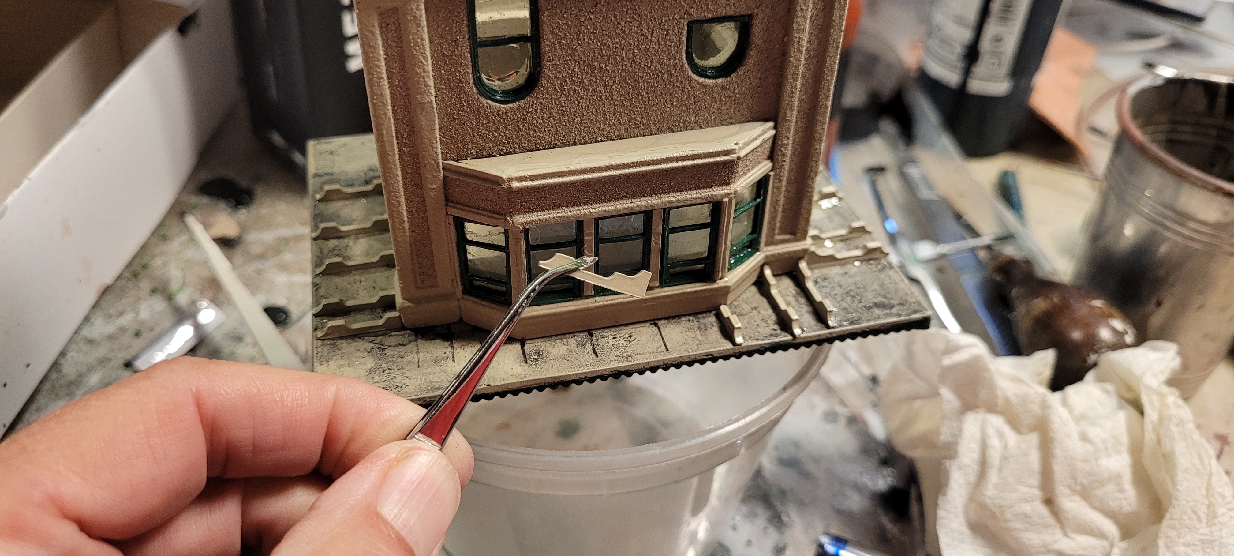
Then I
installed the
bay windows
into the
opening
created
between the
upper bay
plaster
casting and
the lower
metal bay
assembly.
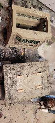
After much
adoo, the bay
windows were
installed.
That was
perhaps the
most difficult
par of the
project.
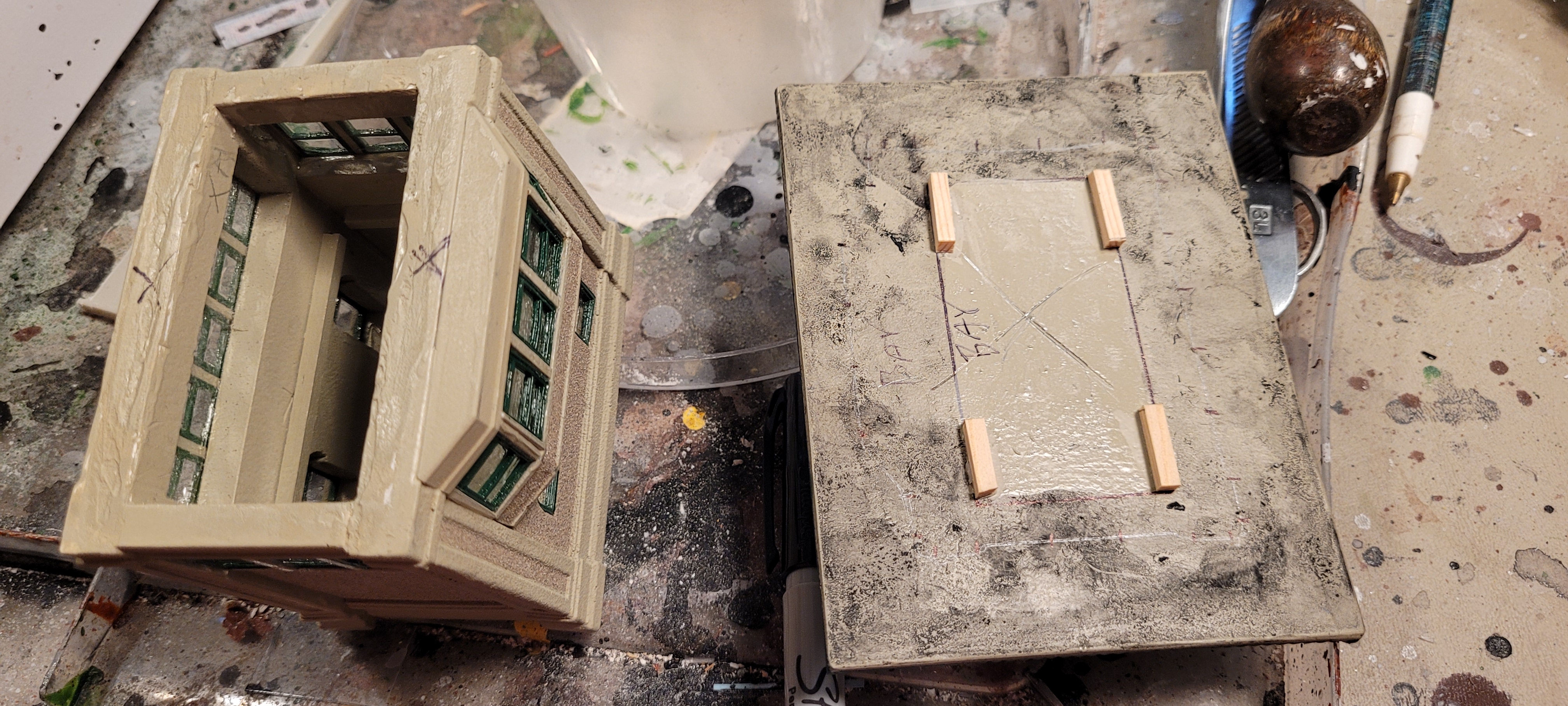
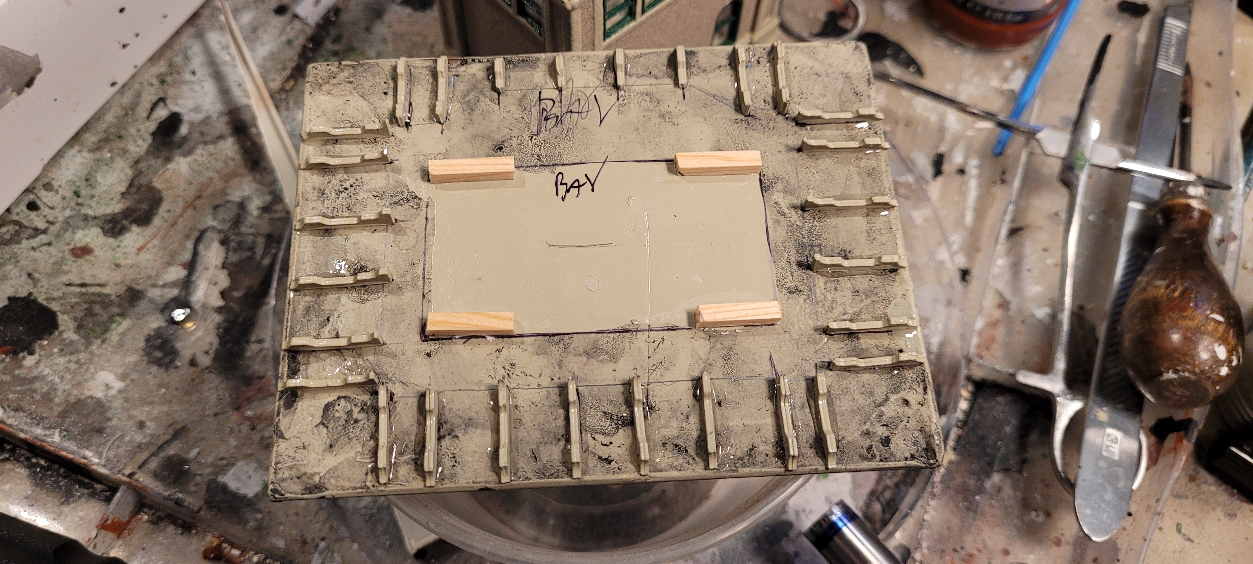
The roof
casting has a
flat bottom
without any
markings.
I had to
establish
where the roof
should rest on
the
sidewalls.
Getting this
centered took
a lot of
measuring and
re-measuring.
I then glued
little wooden
shafts to the
underside of
the roof so
the roof could
be keyed to
the wall
structures.
This allowed
easy roof
removal and
re-installation.
I also glued
some wooden
shafts to the
inside walls
to support the
second floor
which would be
added
later.
The kit came
with a thin
scribed wooden
sheet that I
painted brown
and cut and
fit to the
second floor
area.
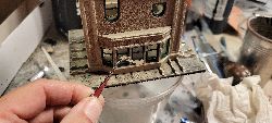
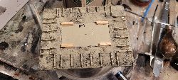
With the building inverted on its
roof casting (supported on a plastic bowl), I proceeded to glue
all the little roof
rafter tails into
position. The roof rafter
tails
needed to be perpendicular to the building and roof edge.
I trimmed the roof rafter tails to fit
between the building and the edge of the building
then and glued each roof
rafter tail in using the UV curing glue.
The original instructions had the roof
rafter tails extending
outwards past the edge of
the roof and the roof
rafter tails
were to support
a tiny wooden
shafts that
would represent
rain
gutters. I
omitted this as
I did not see
fragile wooden
gutters lasting
very long on
this model.
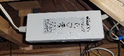
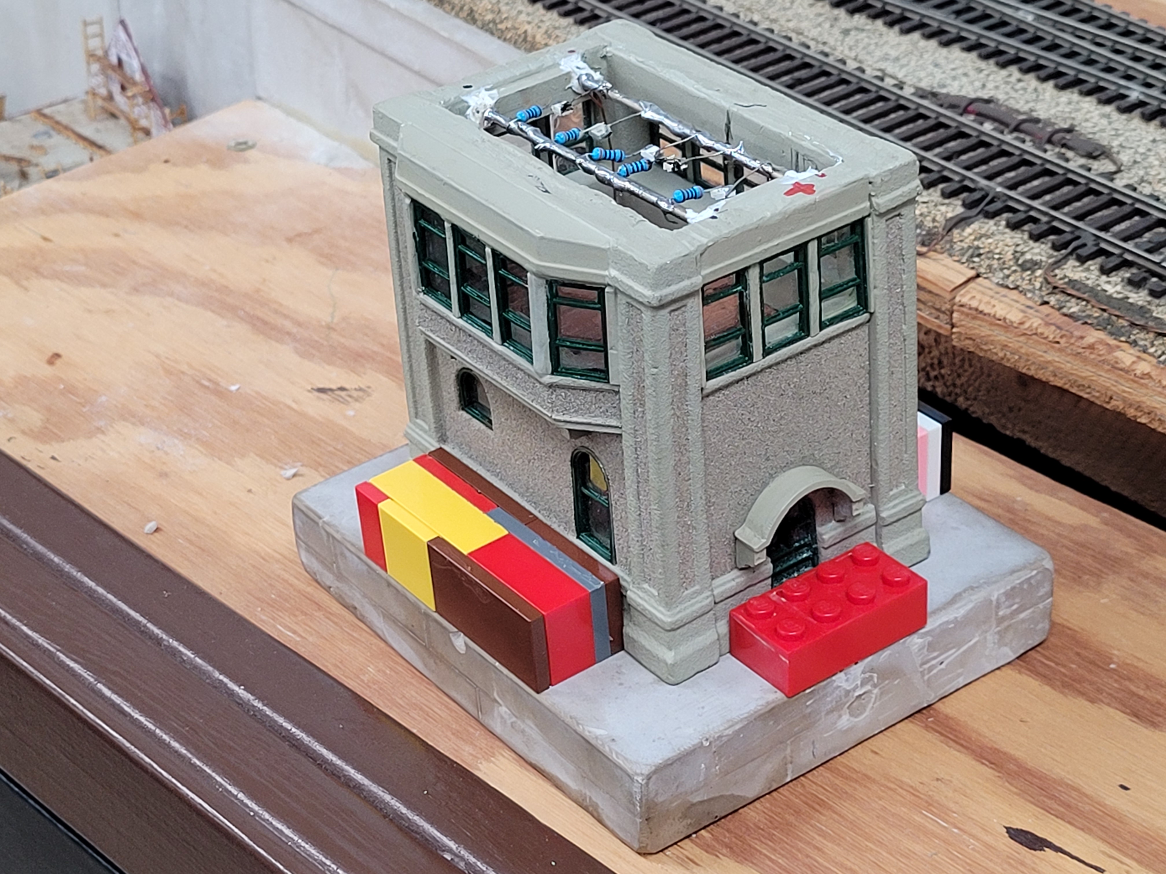
I like to install LED lighting in my buildings. My layout
as a dedicated 12v DC lighting circuit powered by some old
12volt 7.5 amp switching adapter that I had in my junk
pile. It supplies my whole layout's lighting with a steady
12v DC current without flicker.
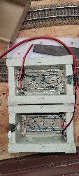
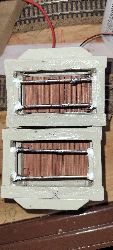
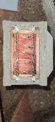
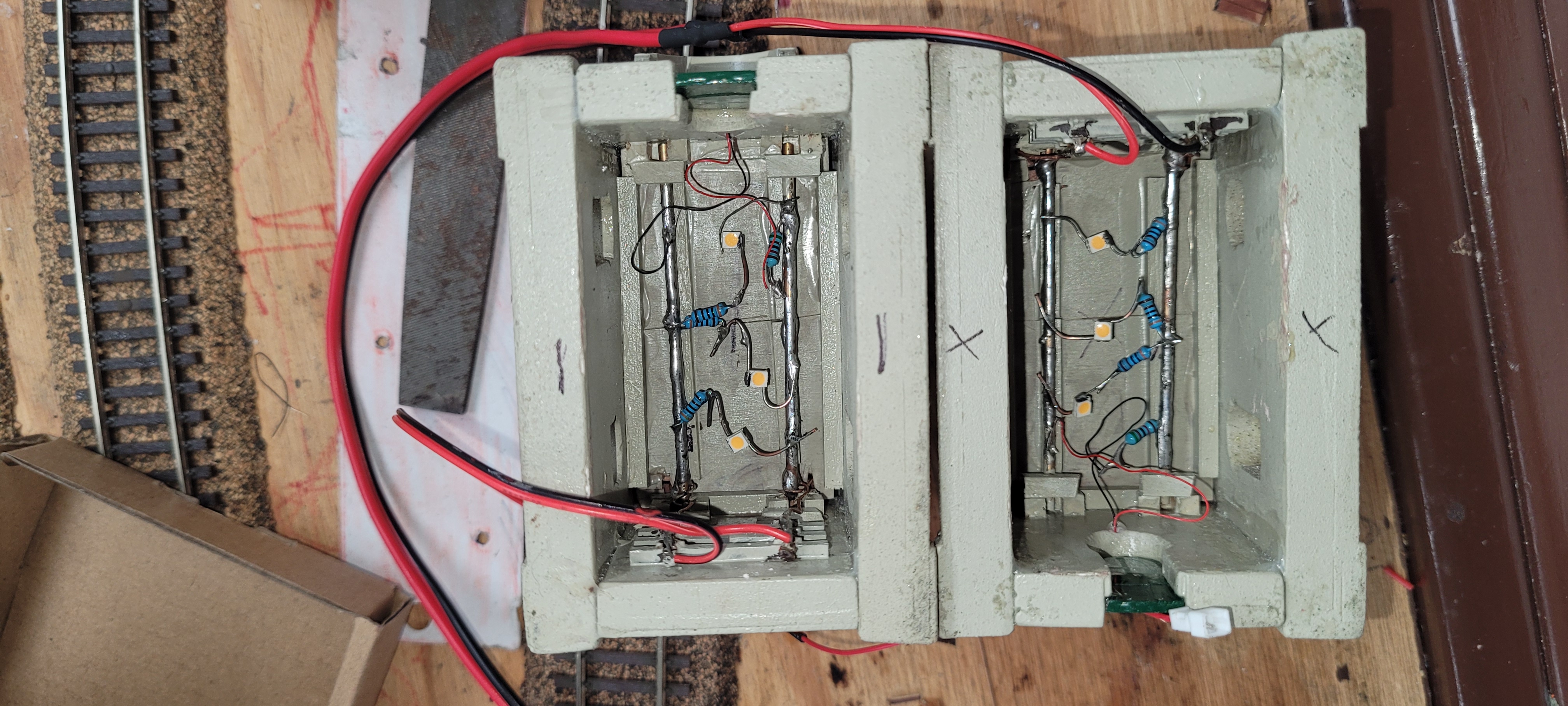
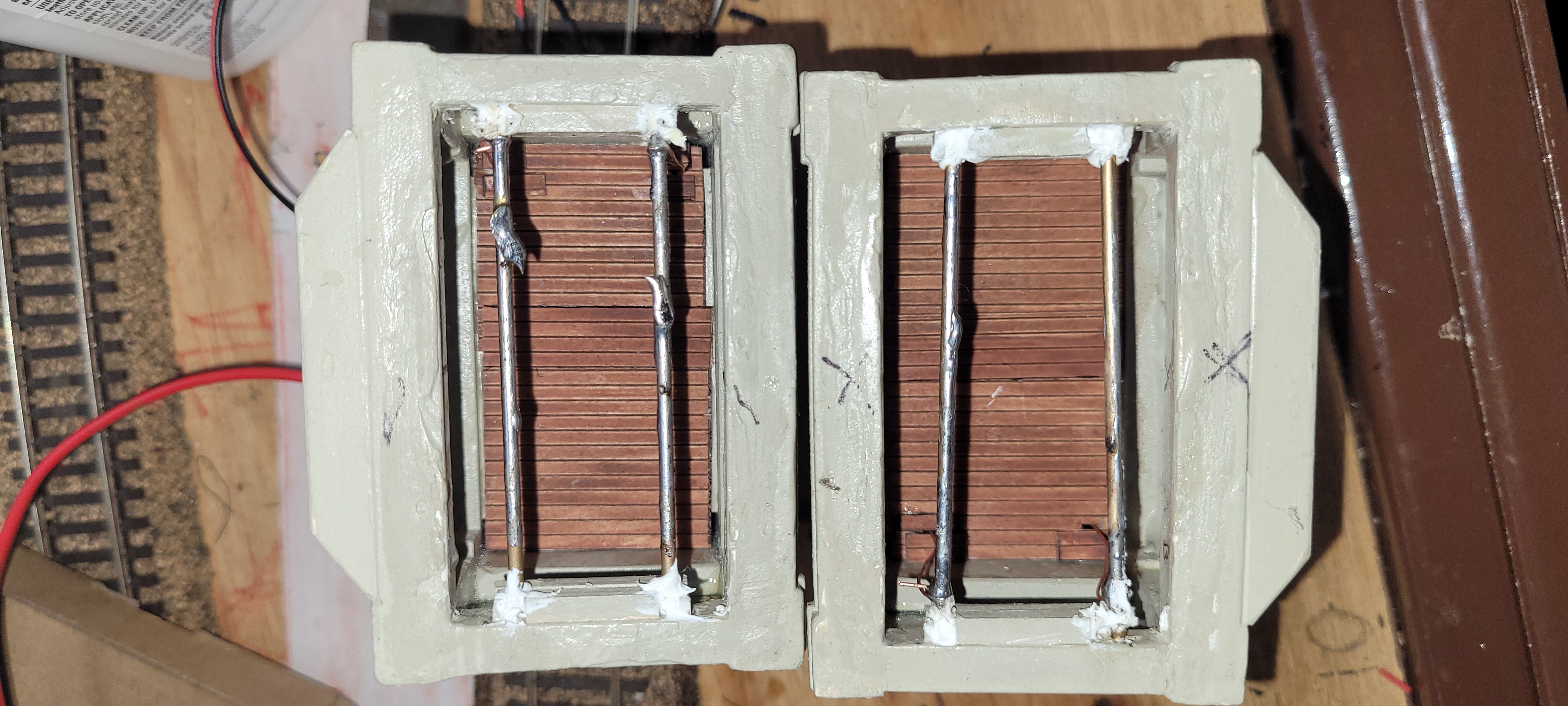
Inside the
tower structure I installed two vertical wires, one for positive
and one for negative. And before I put the wooden second
floor panels in, I mounted two horizontal brass bars which serve
as lighting support and power supply bus bars for the LED lights
that are soldered between them.
The upper level also got bus bars.
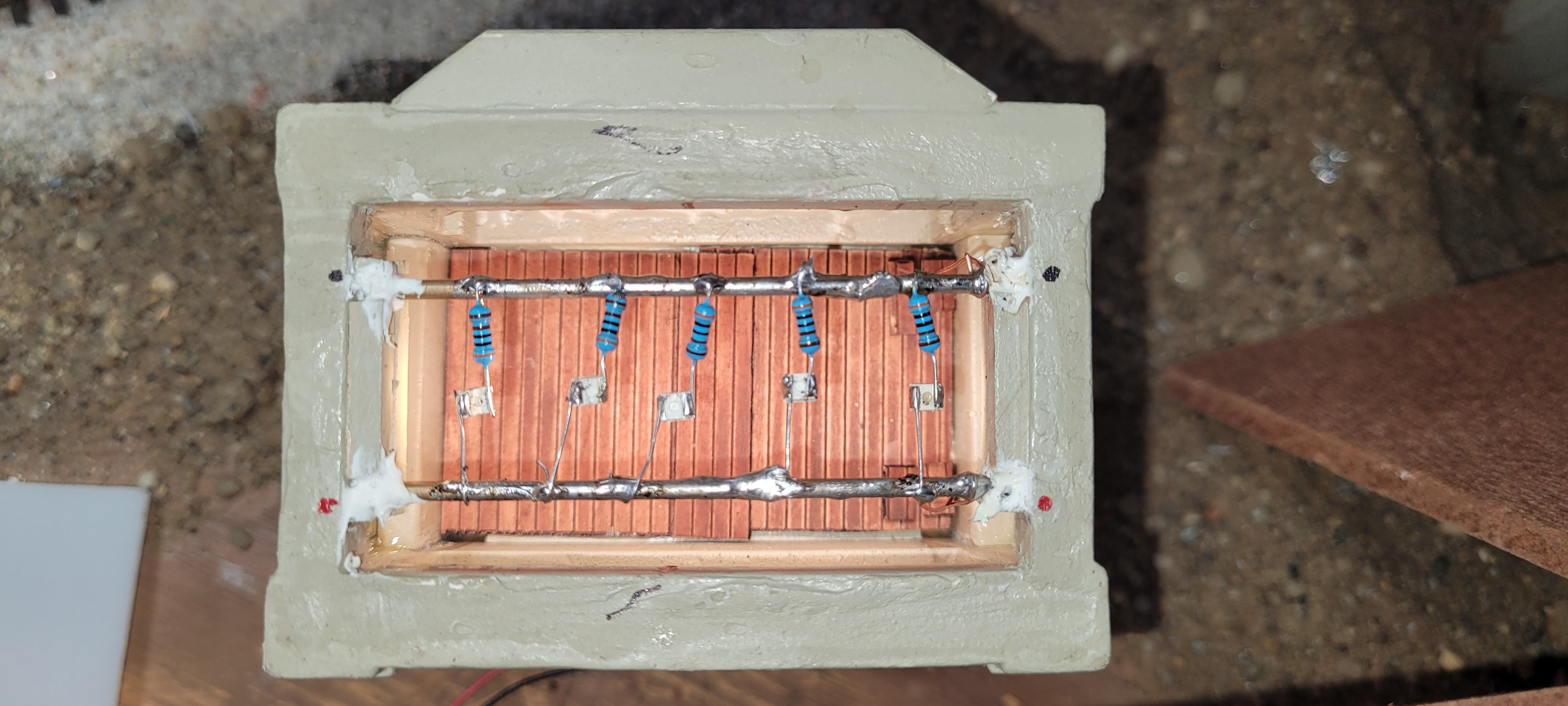
For the single light above the side door, I used a size 0603
Pre-Wired Micro LED, 2.8-3.3V, Warm White. I soldered it
to the power bus bars with a 50,000 ohm resistor in series.
For the other indoor lights in the building, 3 on the lower
floor and 5 on the upper floor, I installed 3030 SMD LED Diode
Lights, Warm White. Each of these were connected to the
bus bar, each having a 3000 ohm resistor in series.
The resistors are essential otherwise the LED's will fail
instantly.
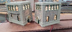
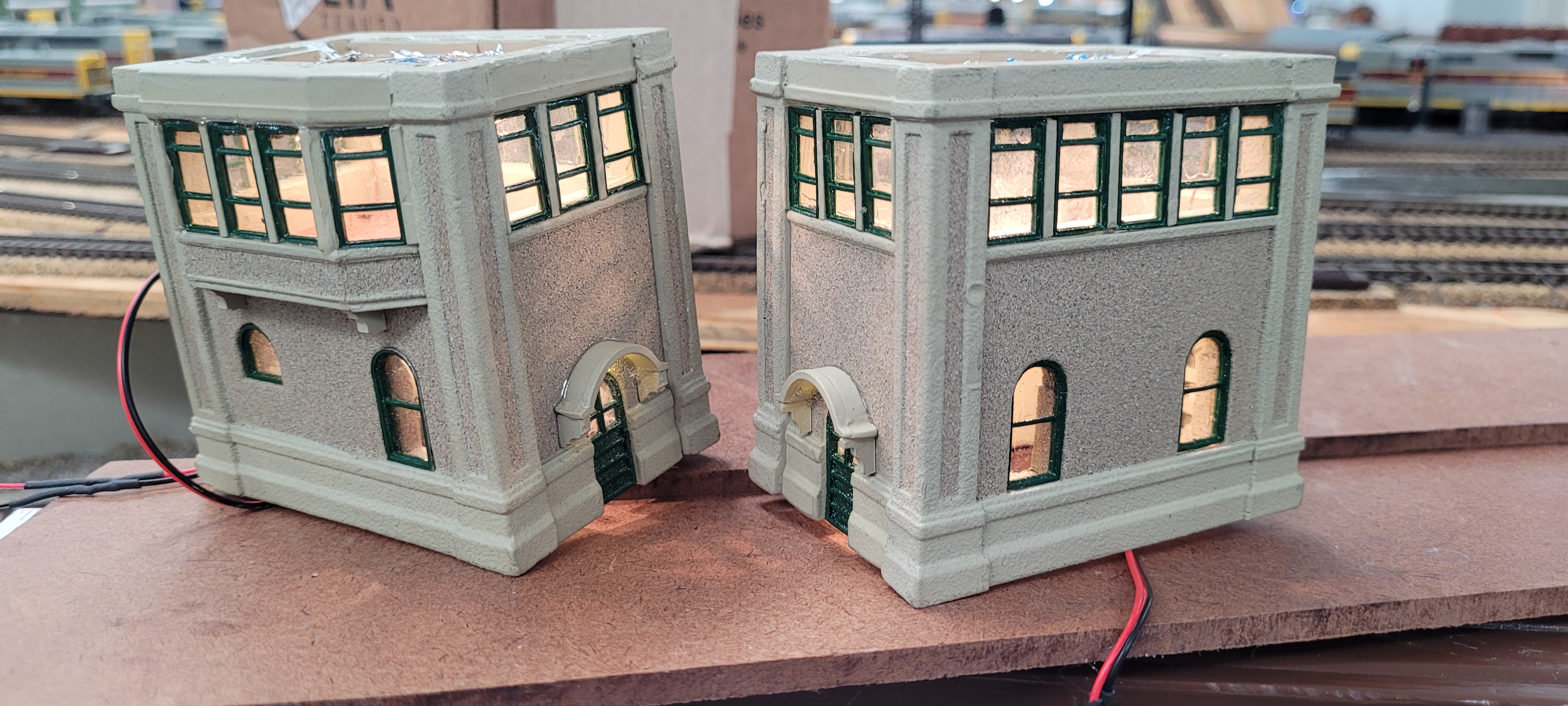
Here is how the lighing looks.
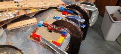
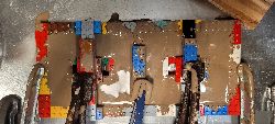
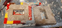
 I decided to make sturdy bases for the
towers. One tower is destined to be a desk display item, the
other tower will be a layout structure.
I decided to make sturdy bases for the
towers. One tower is destined to be a desk display item, the
other tower will be a layout structure.
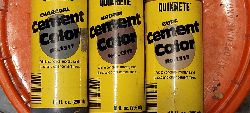
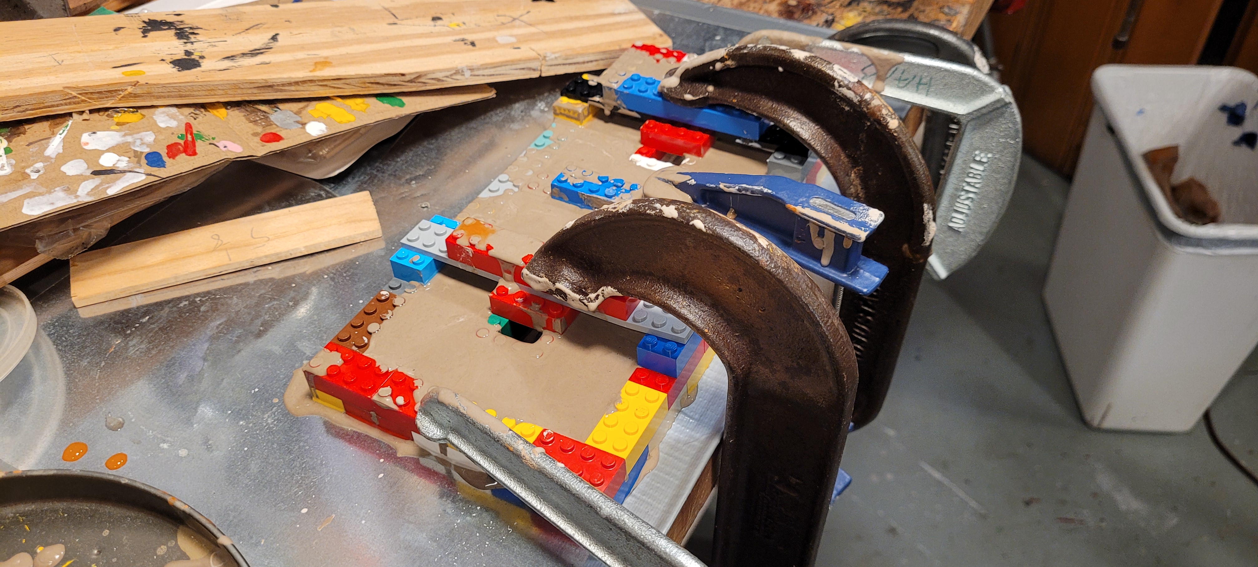
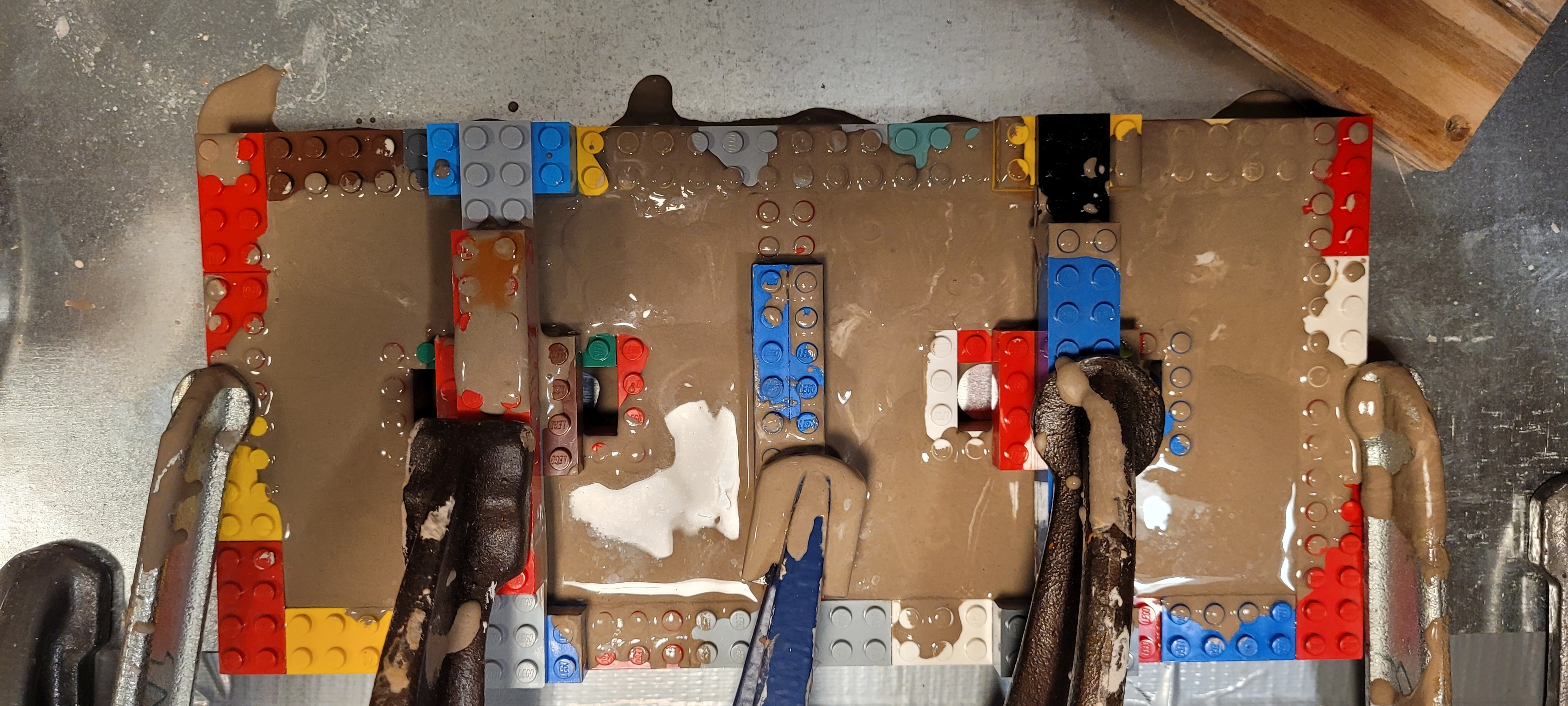
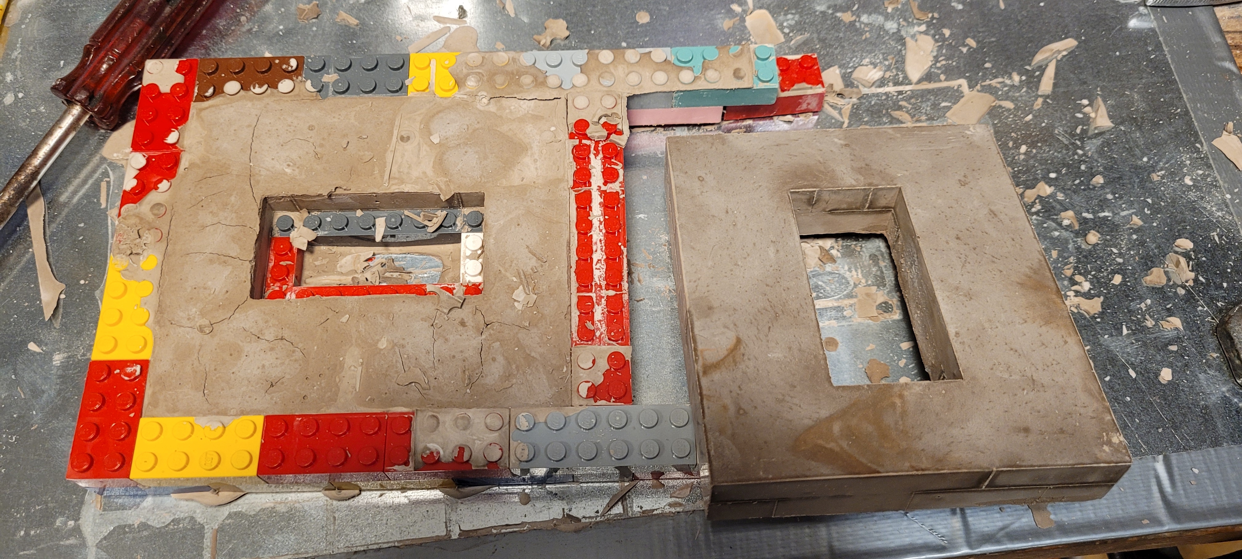
Using Hydrocal, a greased sheet of metal, and Lego molds or forms, I
cast hydrocal into the molds. The hydrocal would be white but
I added pigment to it. My pigment recipe is for each 100cc of
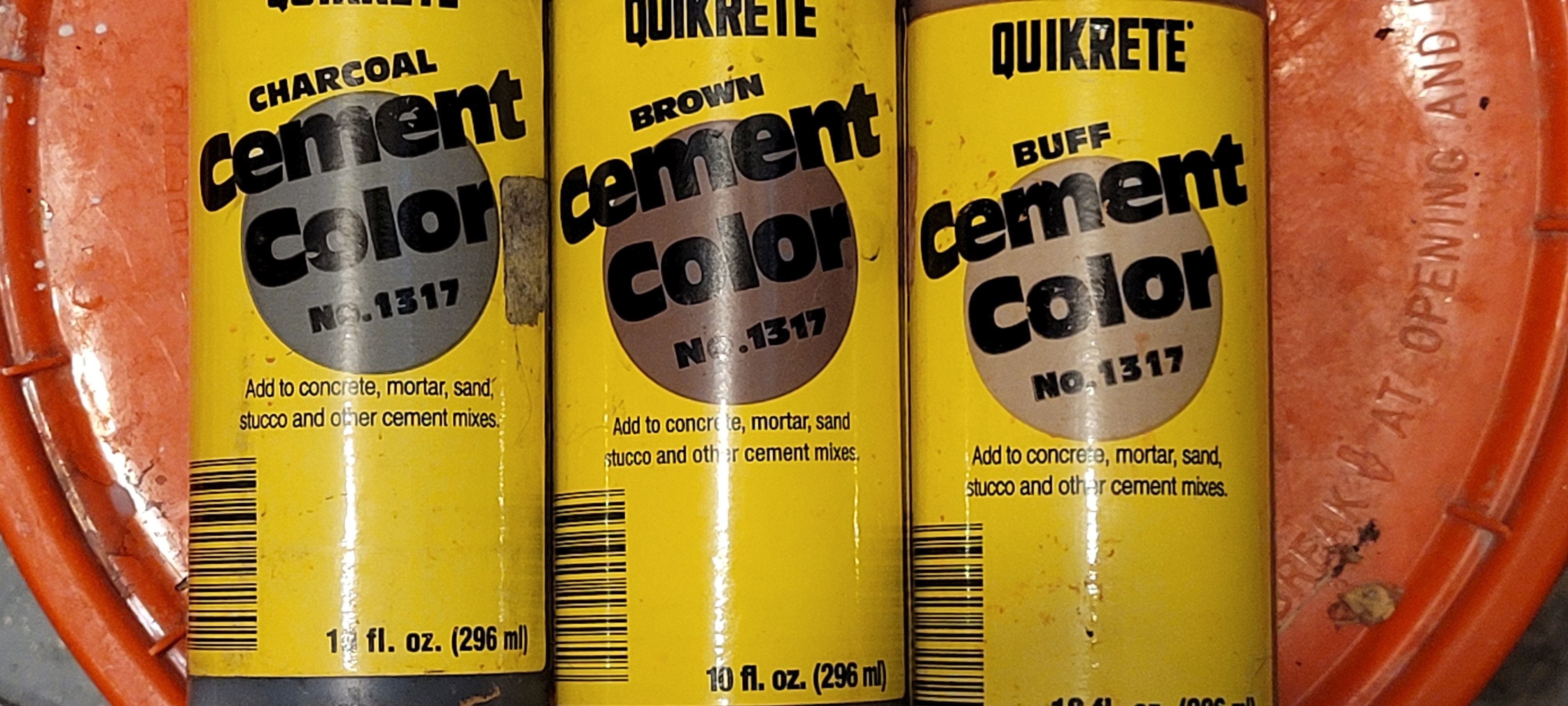
dry hydrocal, I add water, and then I add colorant, (Quikrete Buff
Cement color No.1317 and Quikrete Charcoal Cement color
No.1317). The Quikrete colorant bottles needed to be
vigorously shaken as it settles in the bottles. I added 0.1cc
of each Buff and Charcoal Quikrete colorant into the hydrocal
mixture.
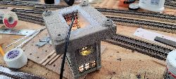
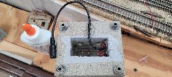
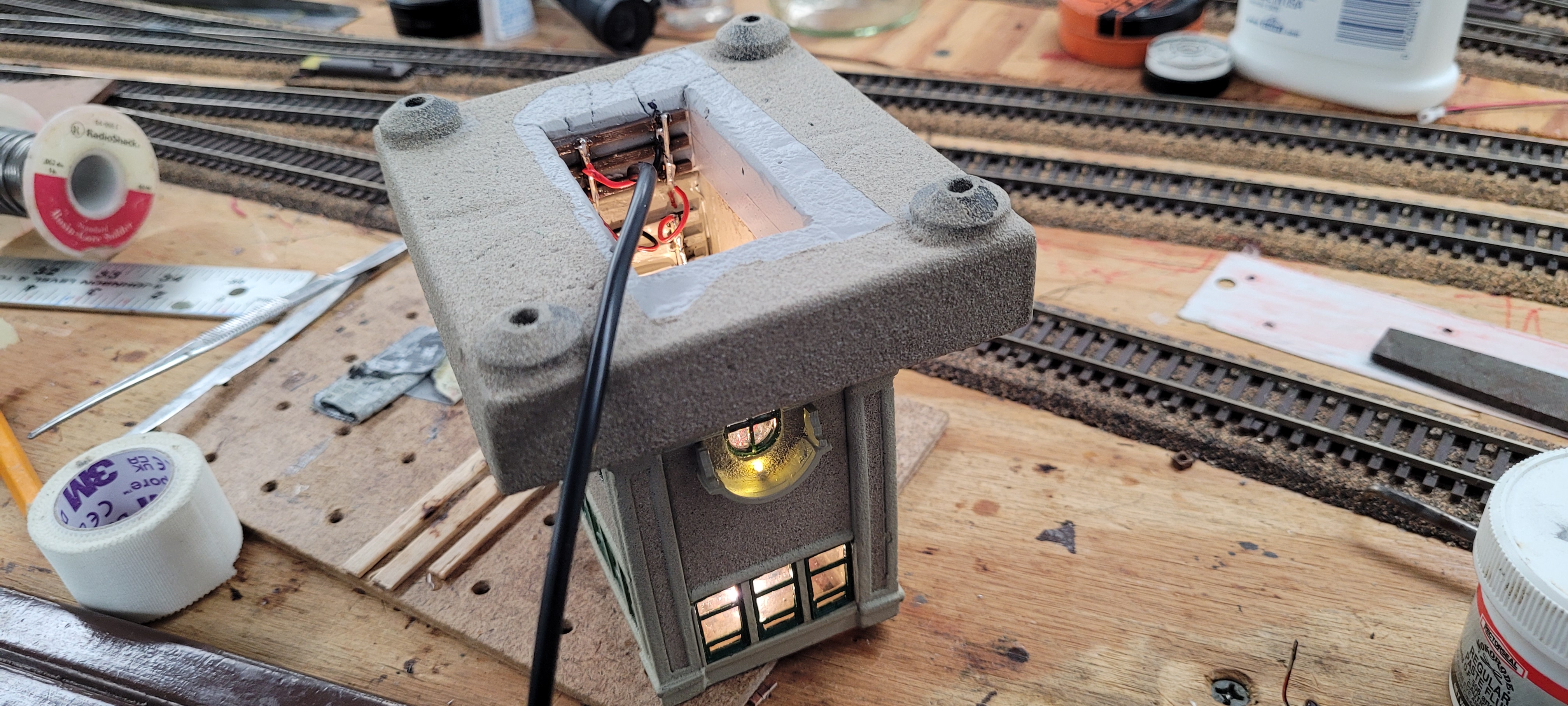
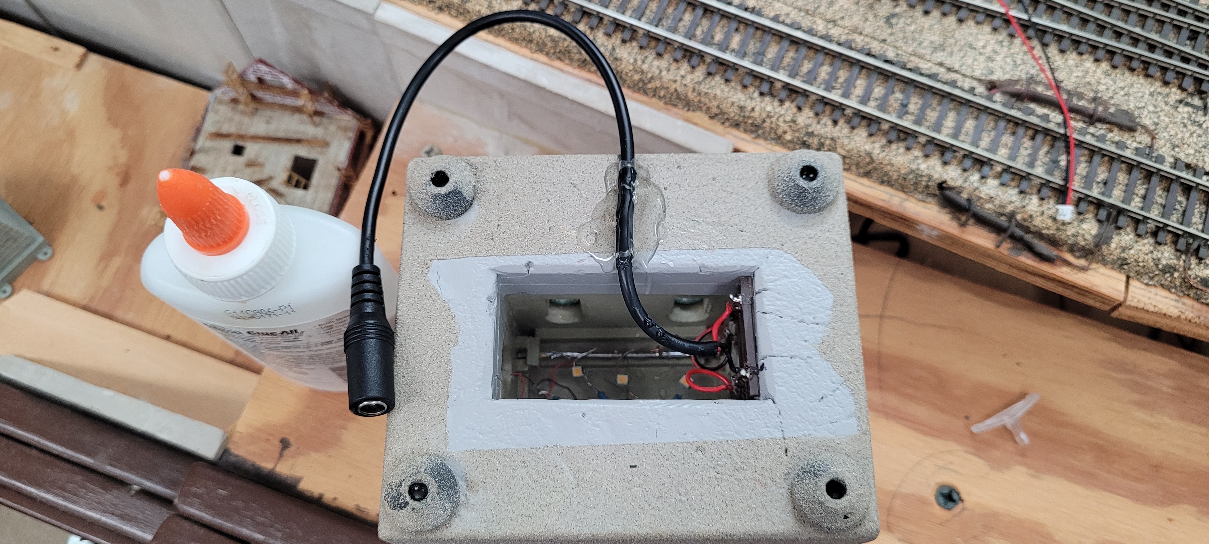
Here we see the future desk display tower with the base attached and
the power wire coming out the bottom.
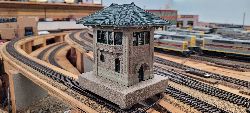
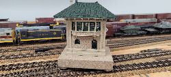
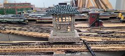
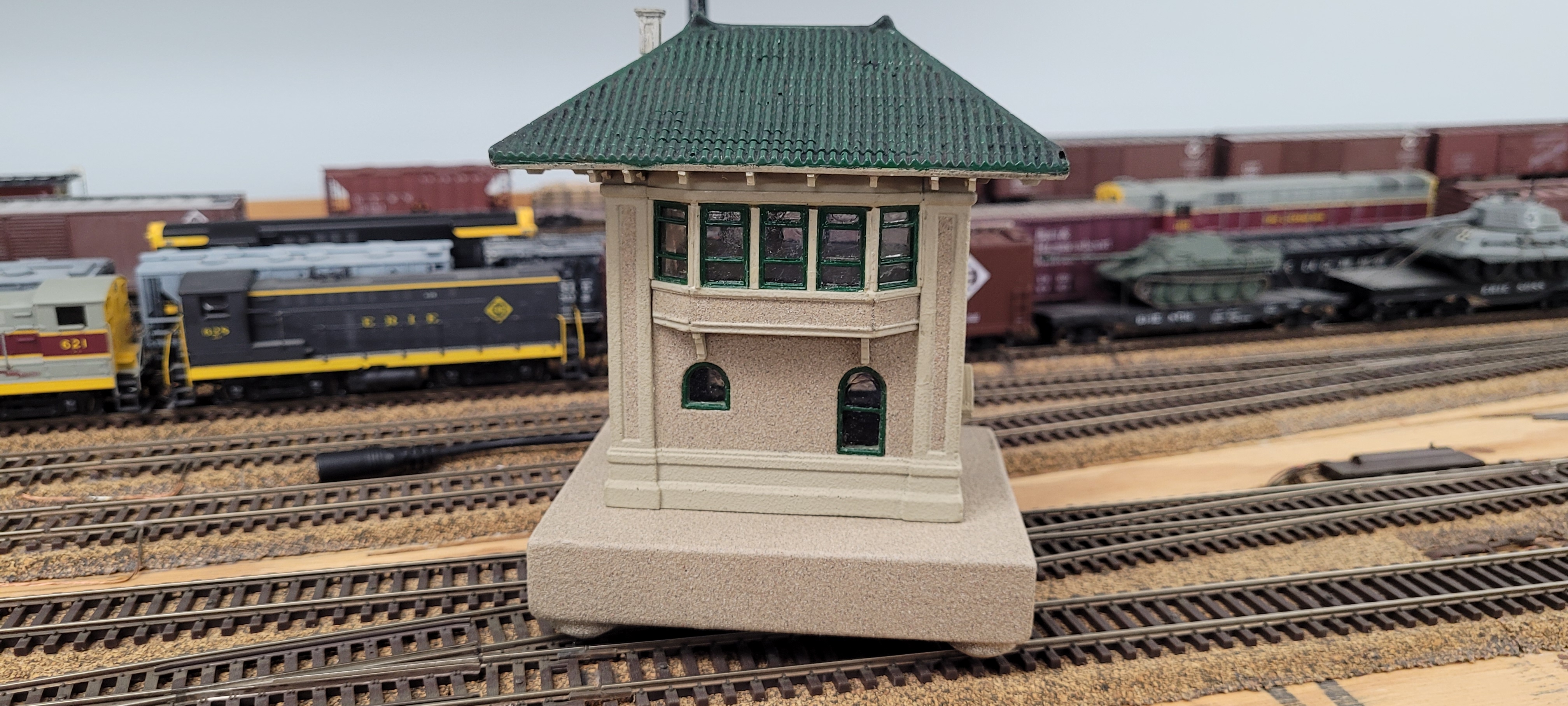
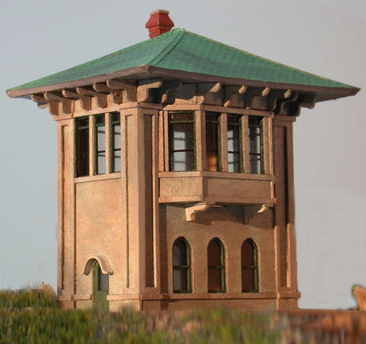
Here is the desk display model tower with roof with chimney and the
base attached. The base was sprayed with Rust-oleum Mutlicolor
Textured "Desert Bisque".
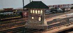
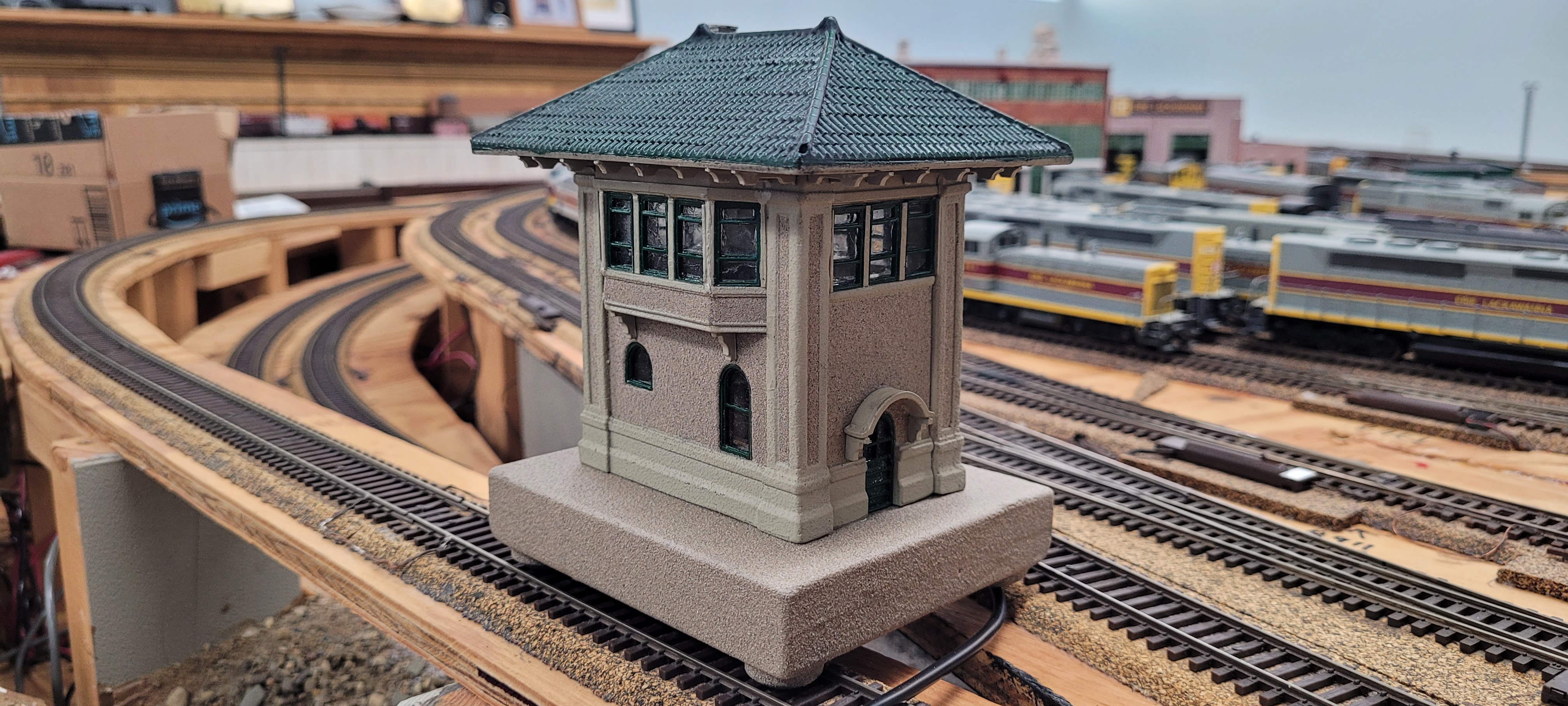
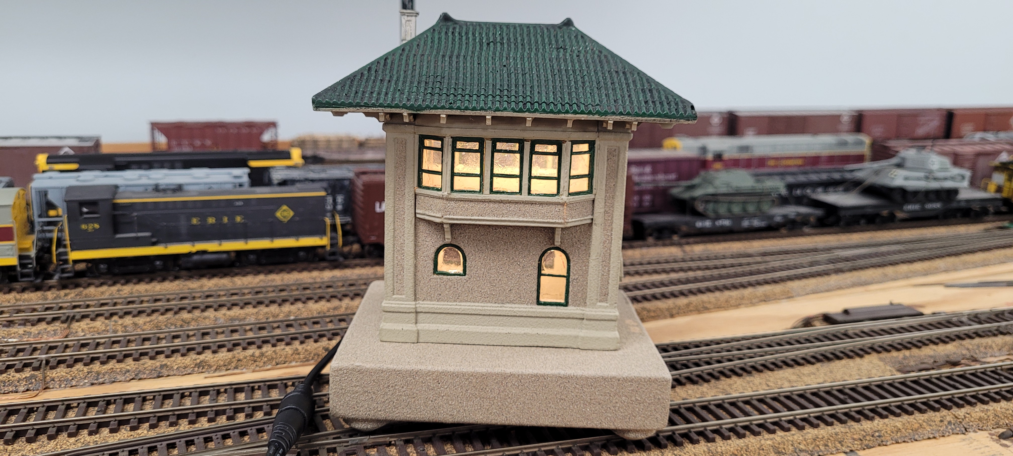
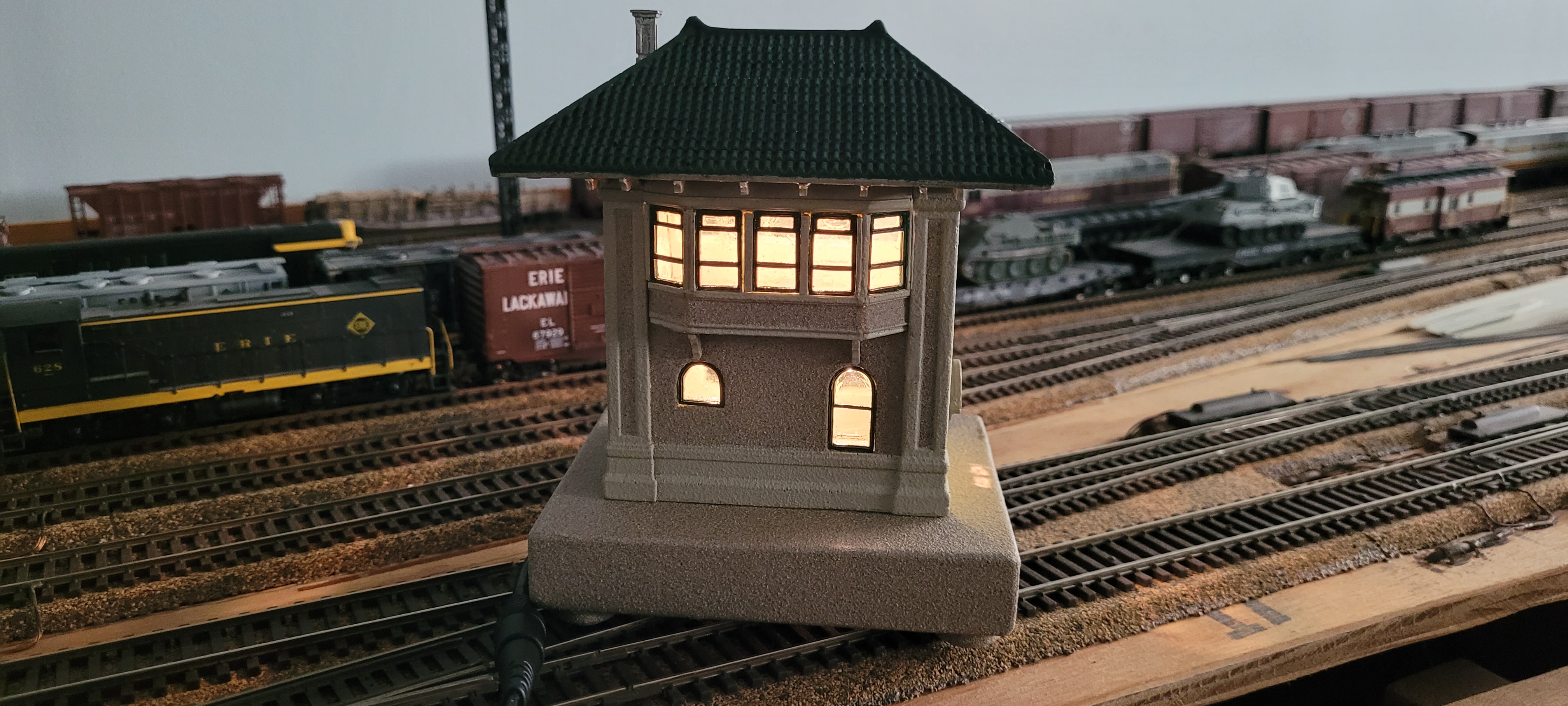
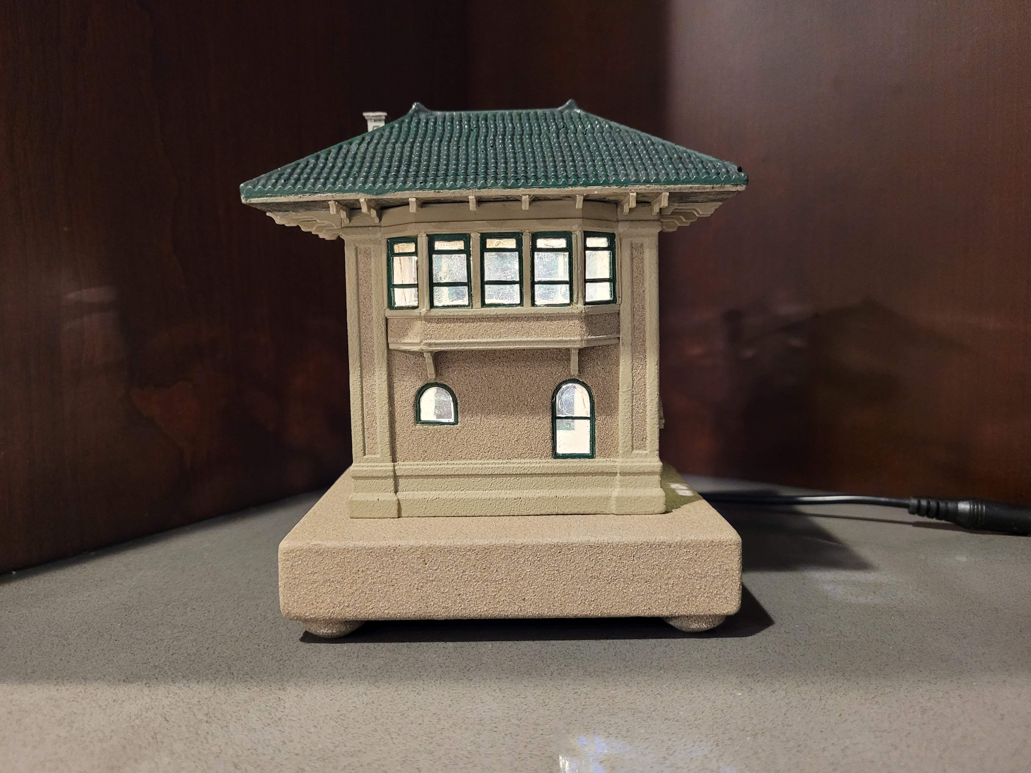
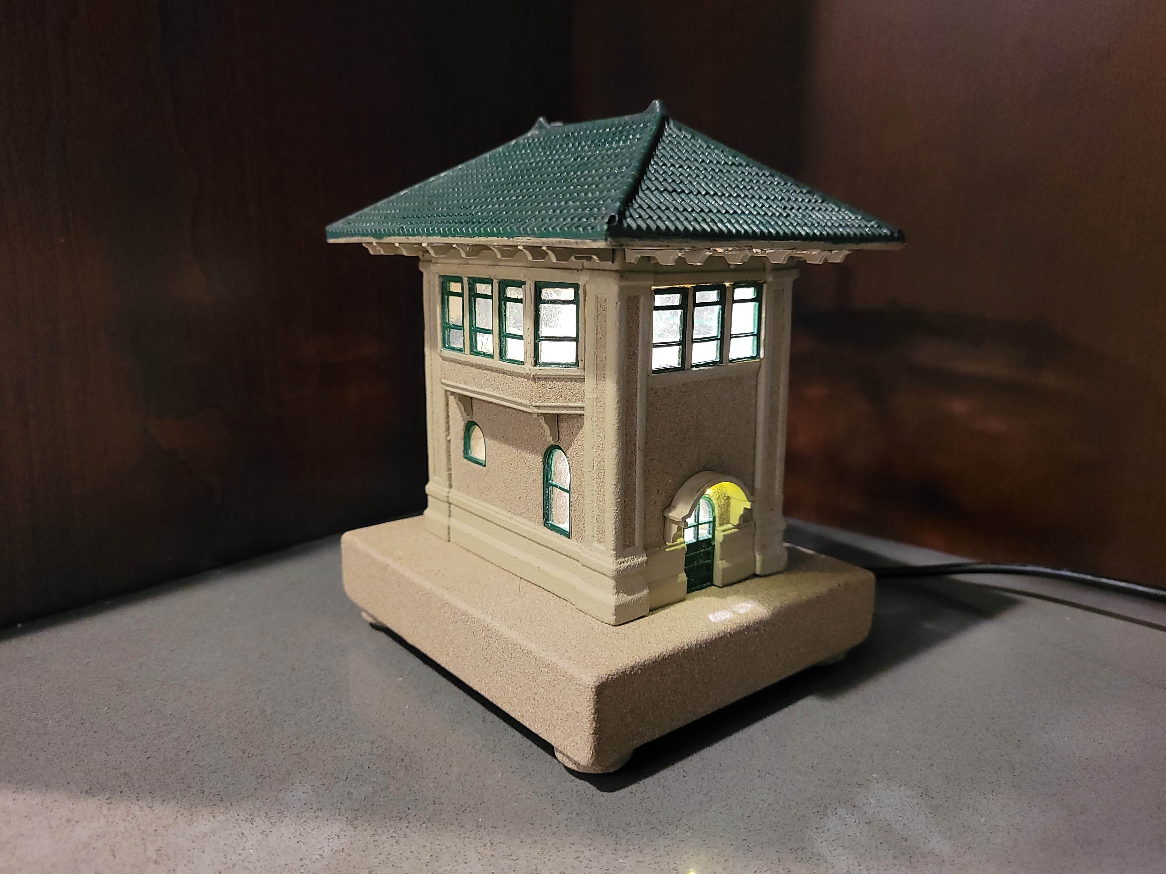
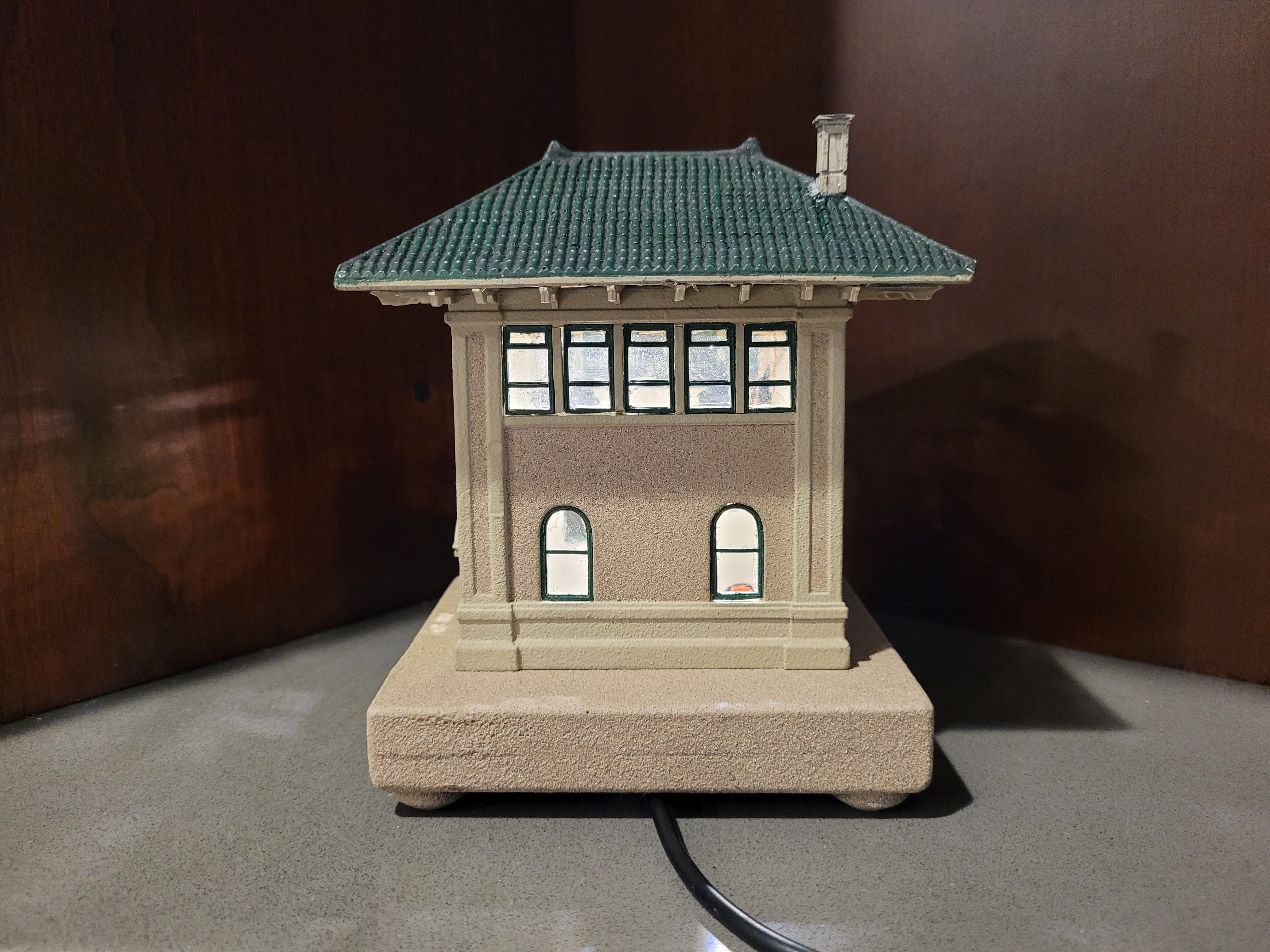
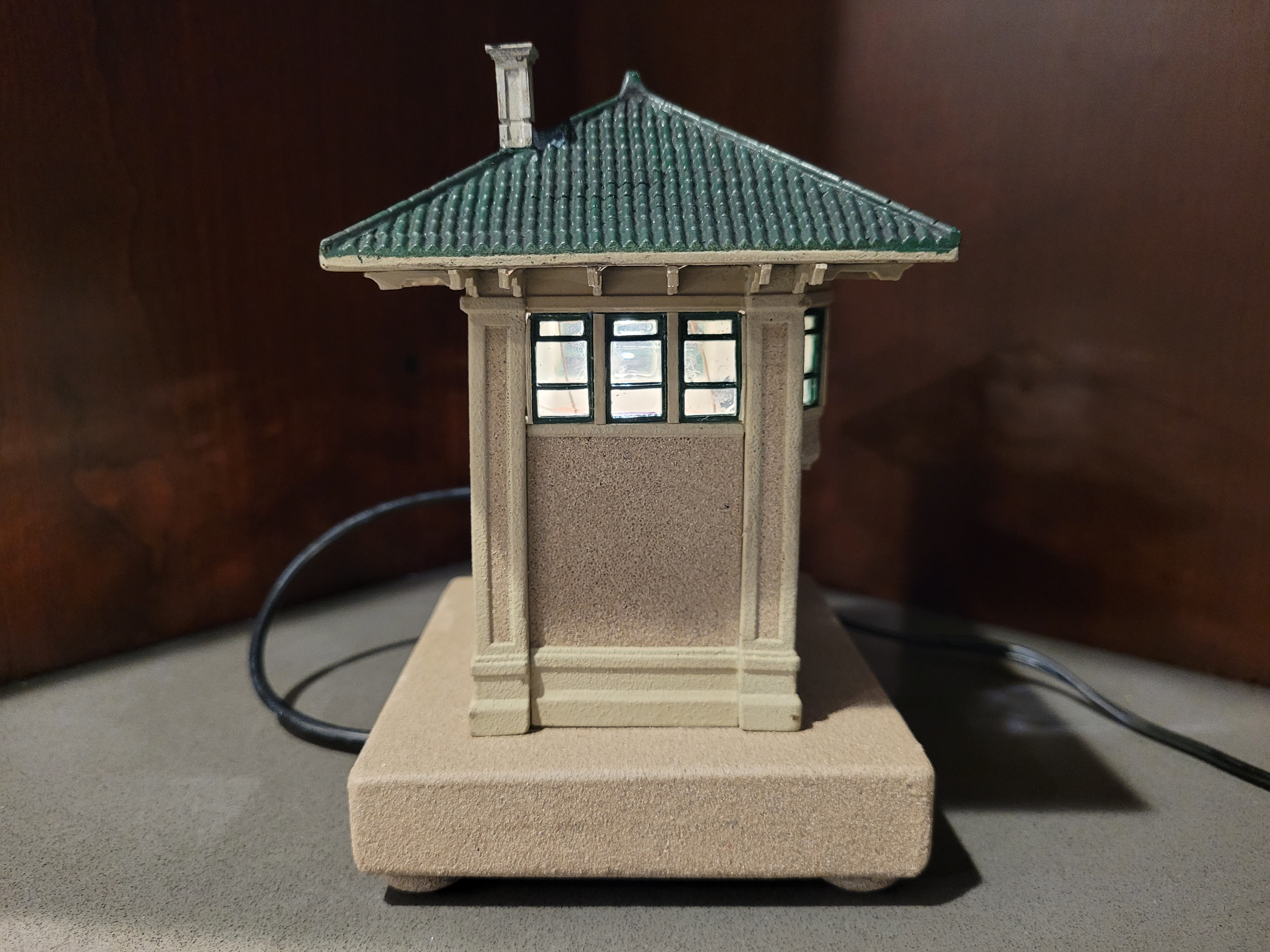
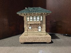
Some more views of the desk display model tower upon completion.
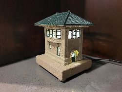
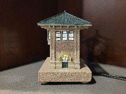
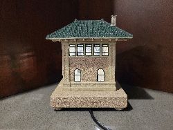
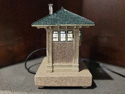
And some views of the display tower displaying itself.
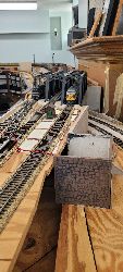
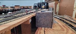
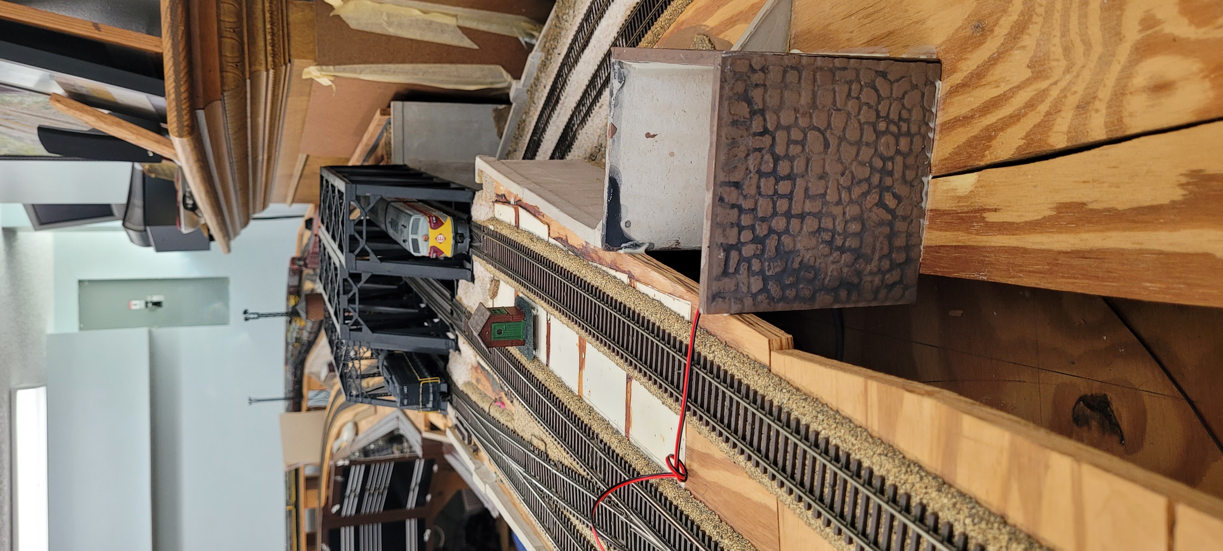
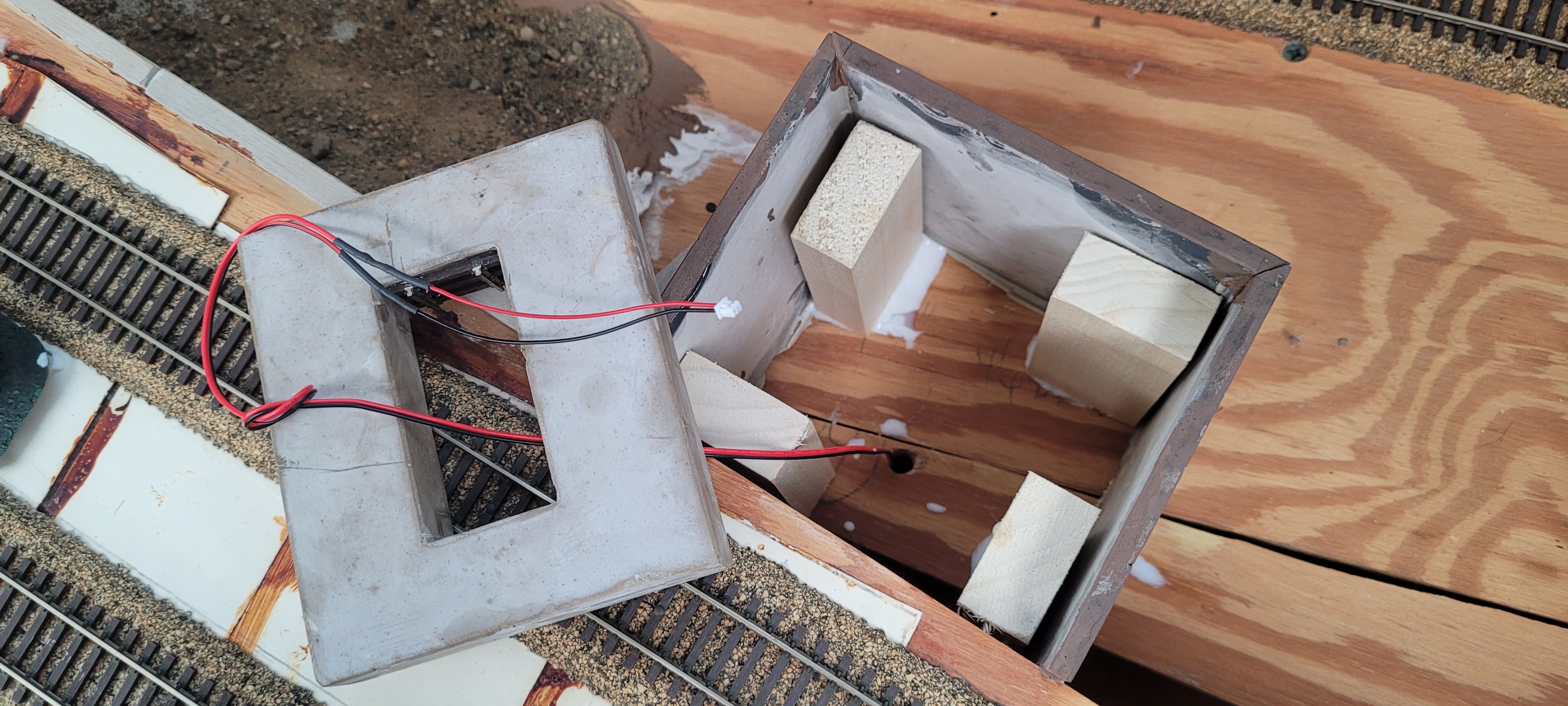
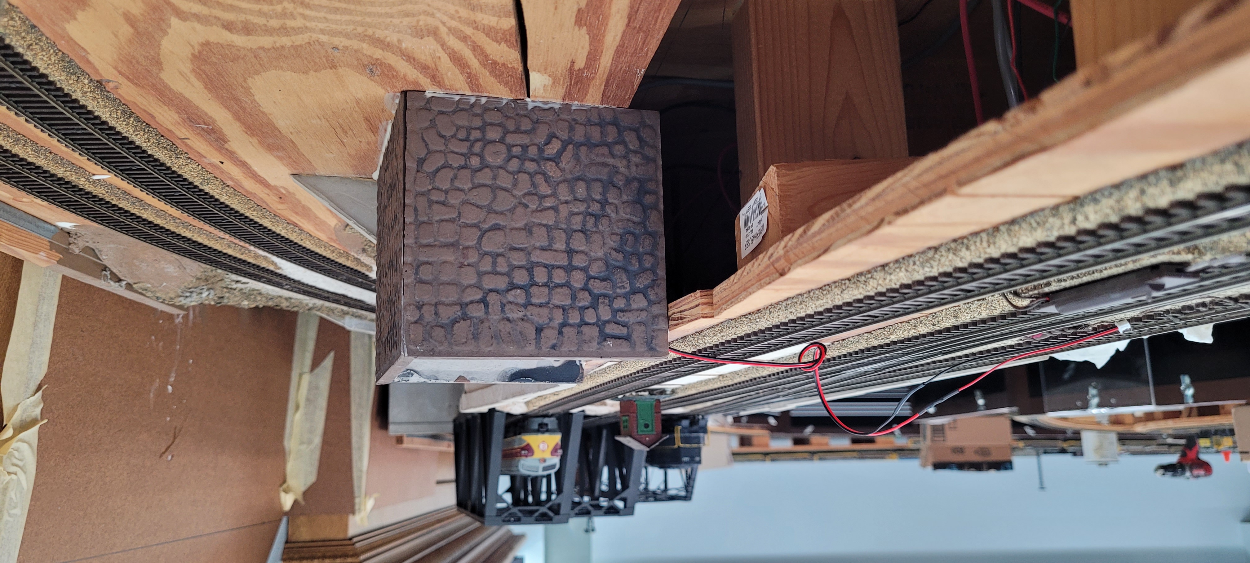
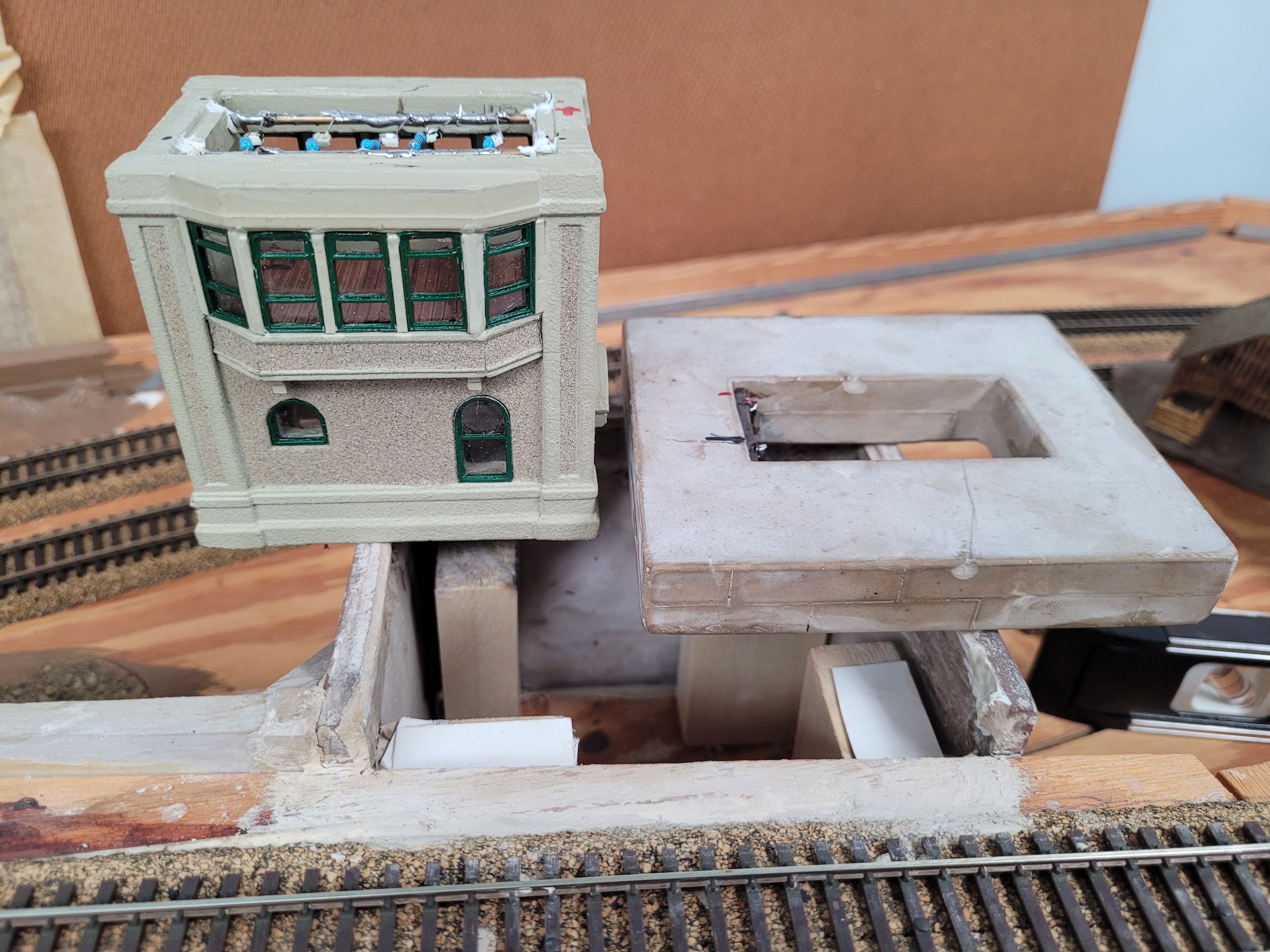
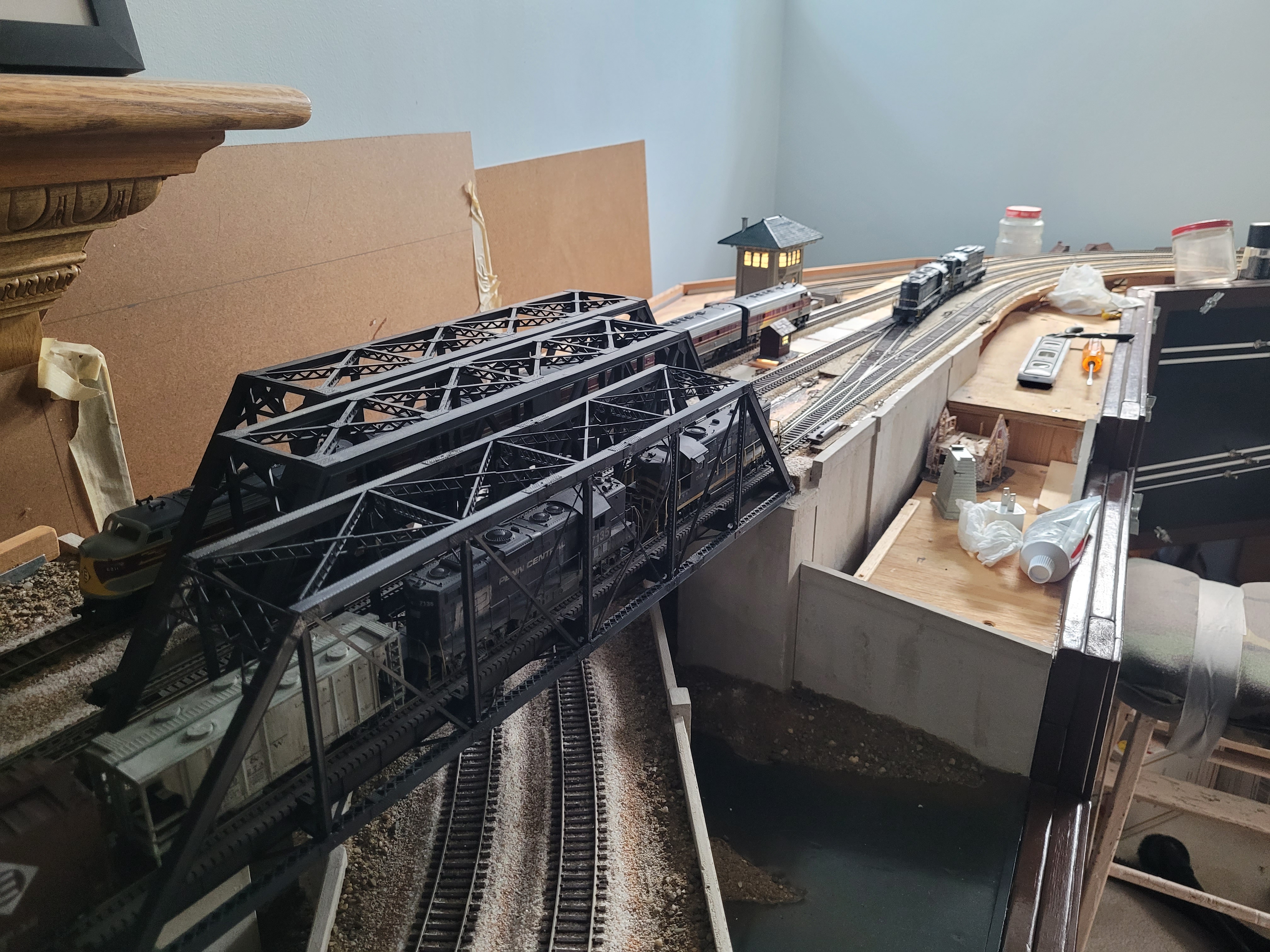
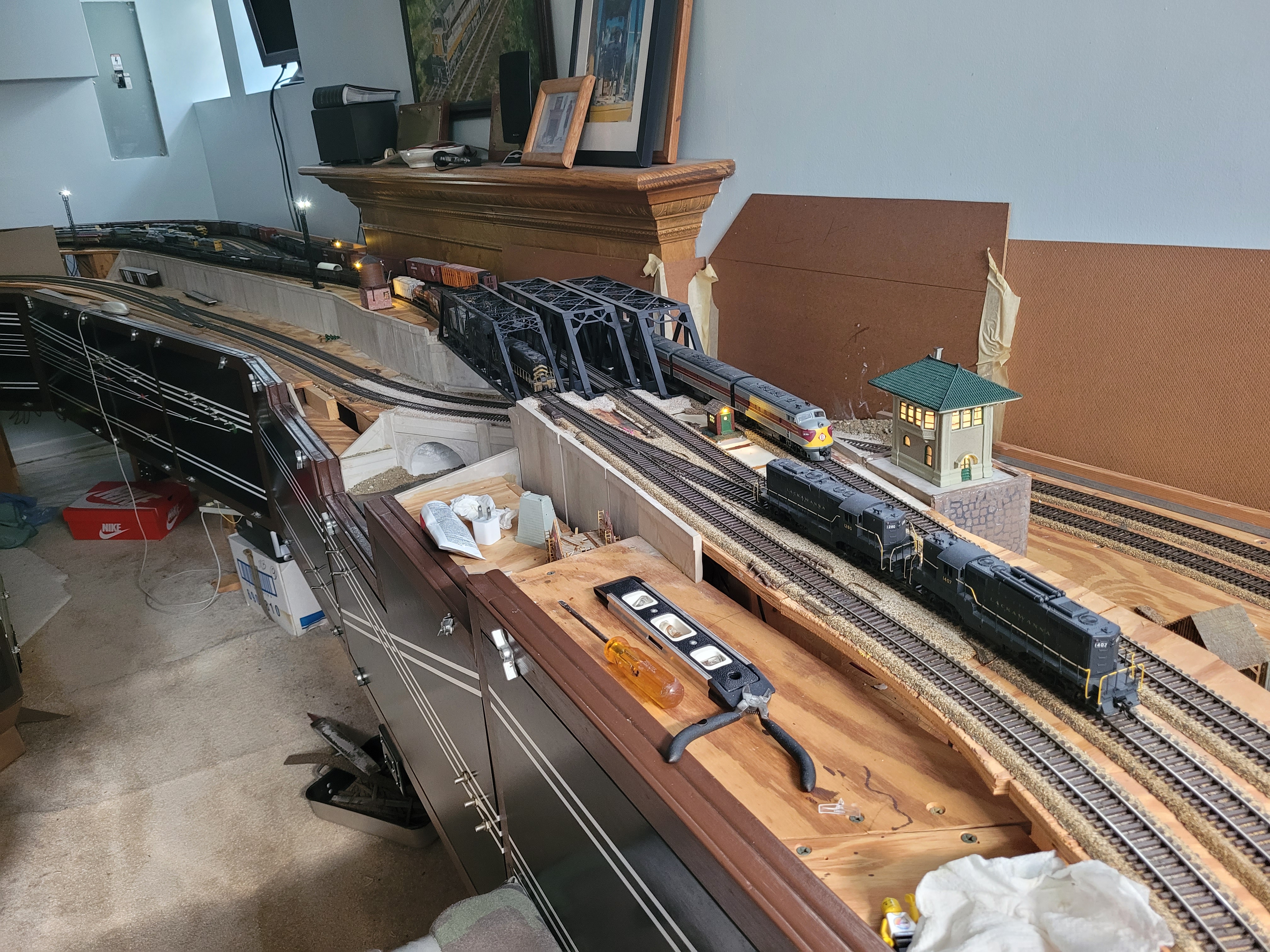
The second tower model was destined to be placed in this layout
location on a built up foundation made of hydrocal castings.
The tower's base casting was used as the dimensional template for
the foundation perimeter.
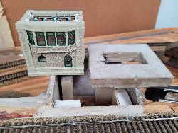
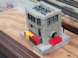
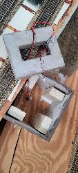
Here is the tower, and its hydrocal cast base. Using Lego
pieces to center the tower onto the base, I used Elmer's glue to
glue the tower to the base casting.
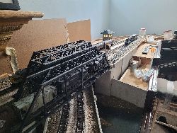
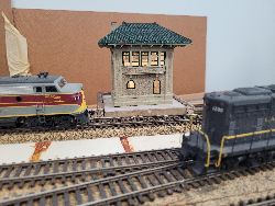
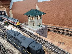
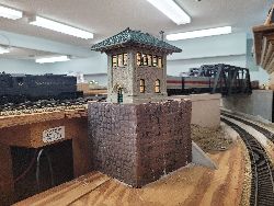
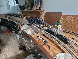
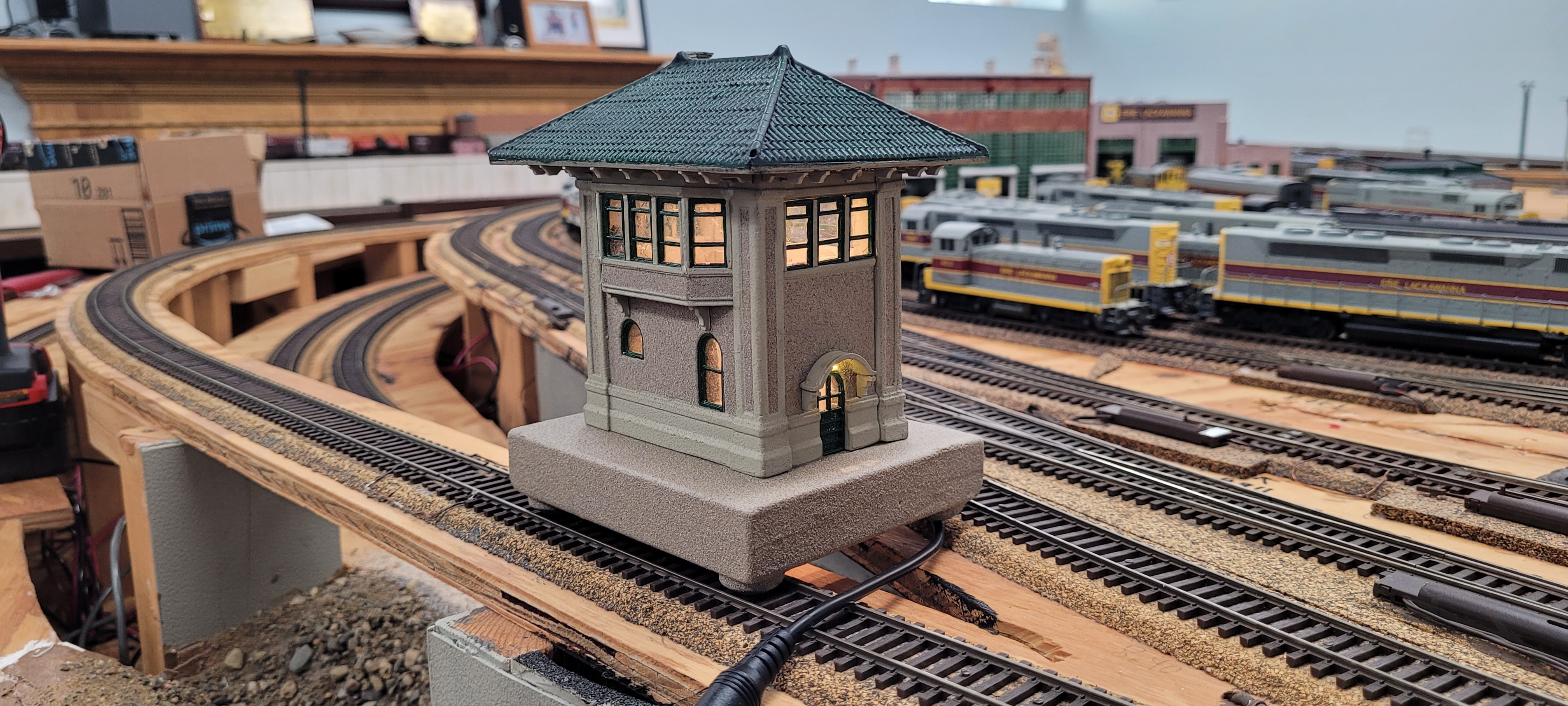
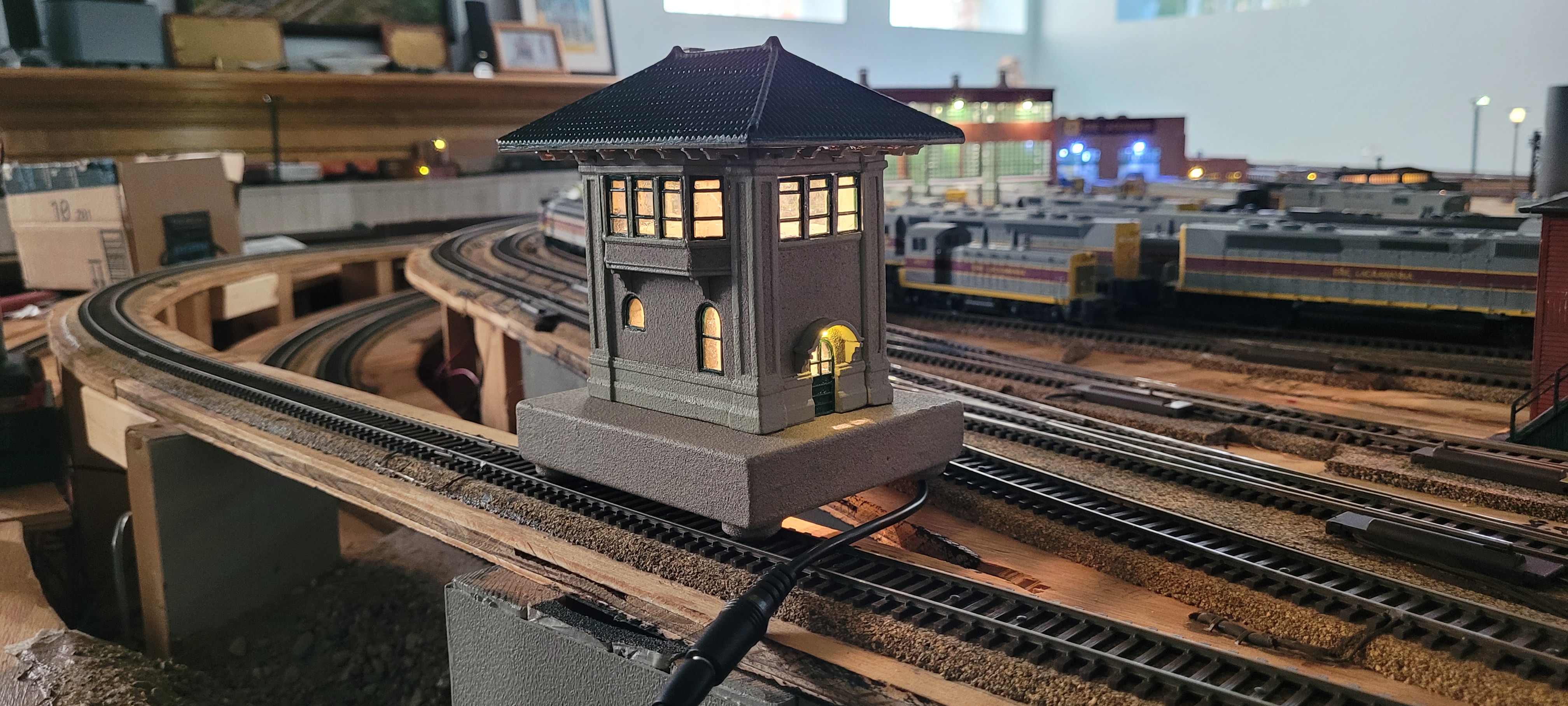
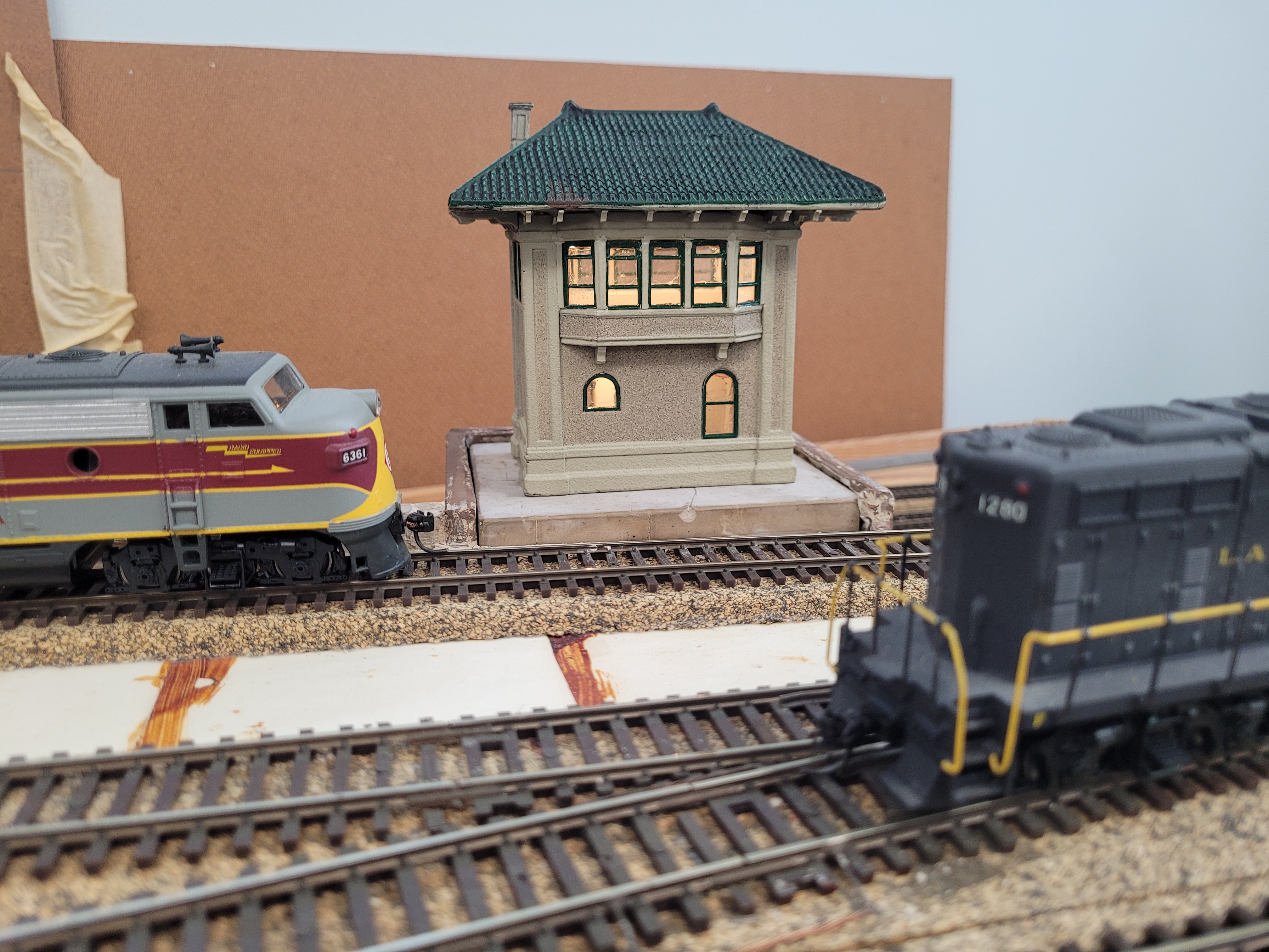
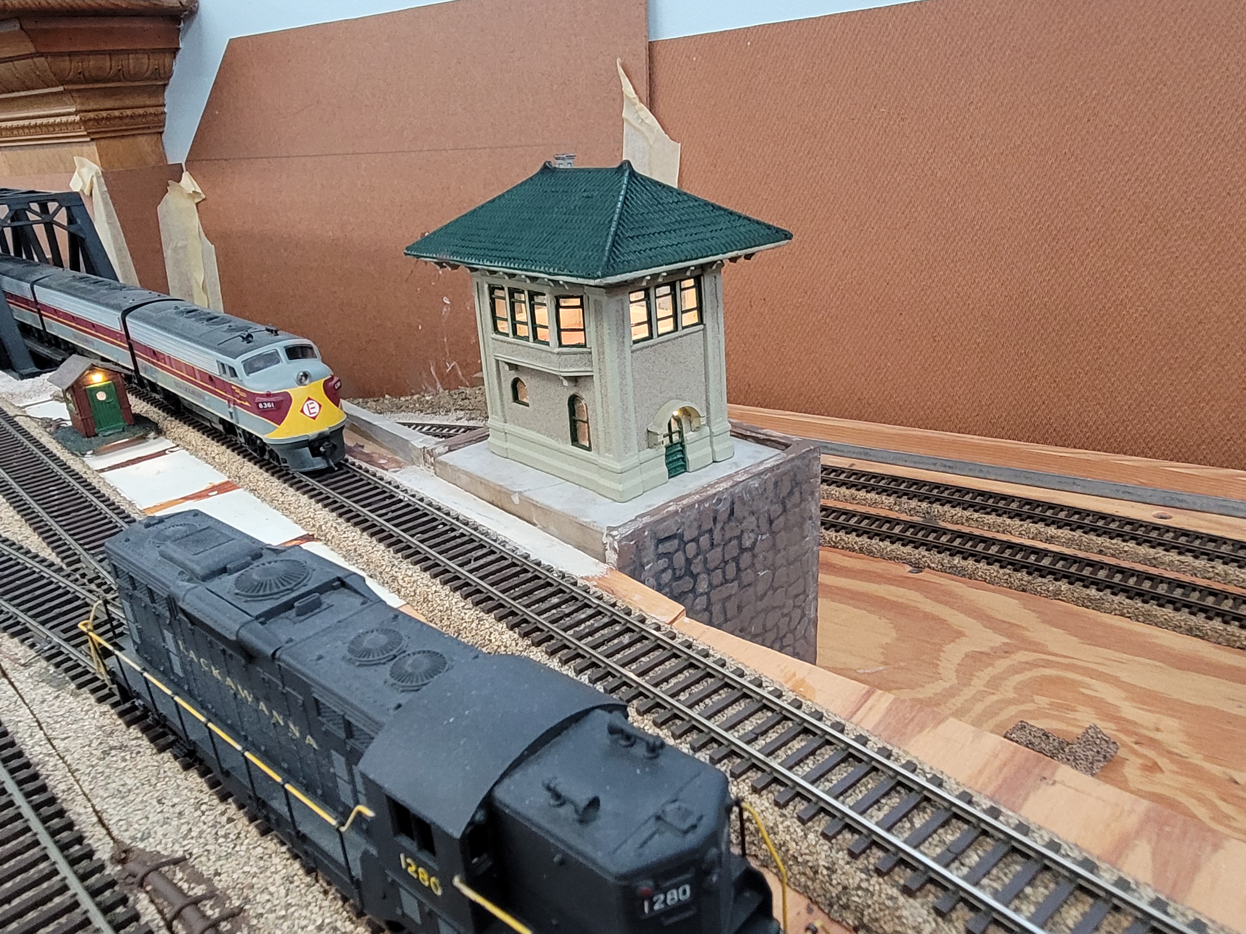
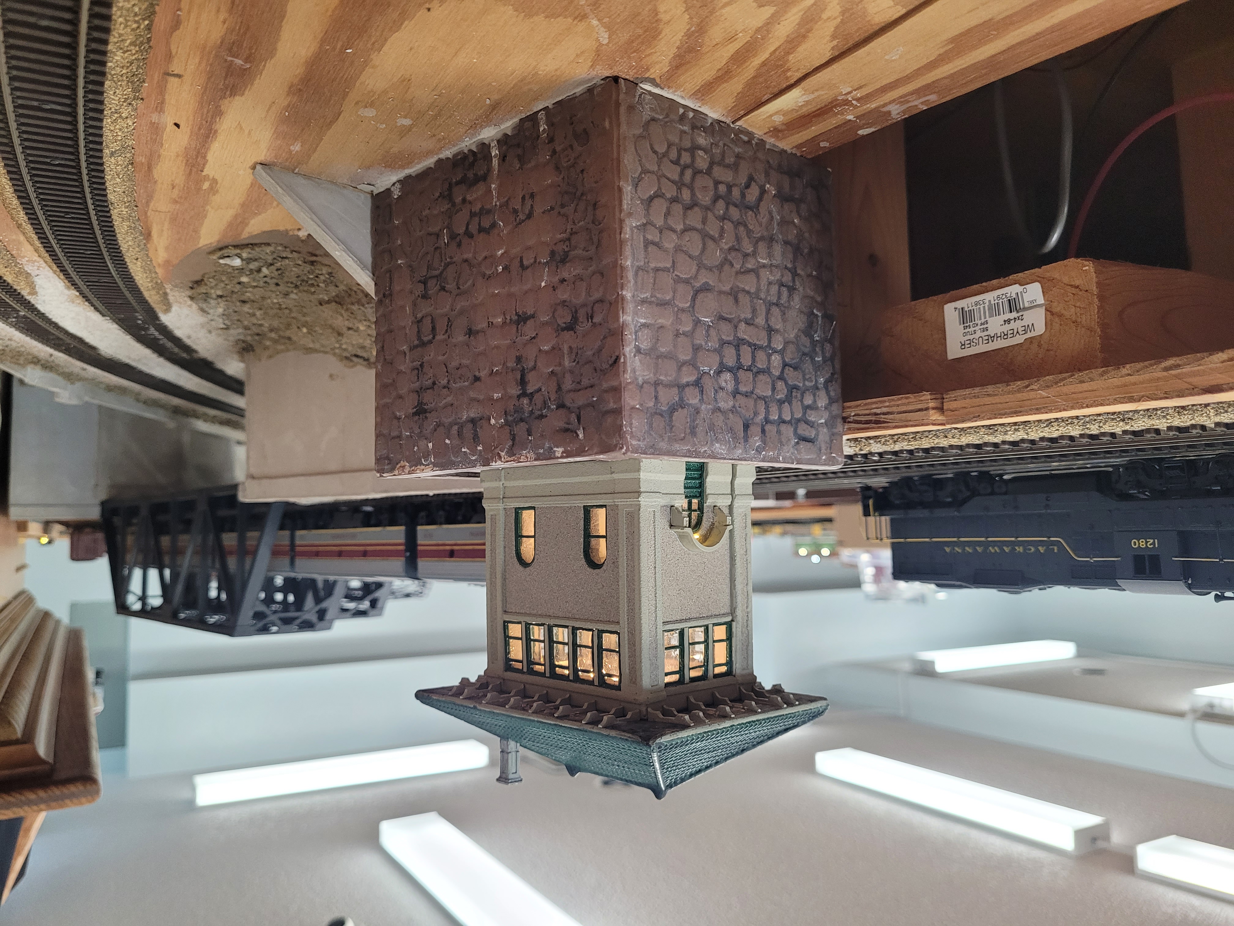
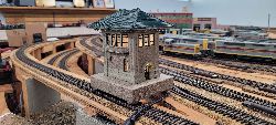
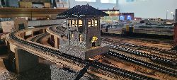
The tower seen here in its location. Lights are on, the roof
is installed, let the trains roll.
Email: axm11@case.edu
Return to: Morscher's
Railroad Images Page
 and
Greendell, NJ. The Lackawanna had some wider concrete towers which had and additional windows on
each side of the bay window.
and
Greendell, NJ. The Lackawanna had some wider concrete towers which had and additional windows on
each side of the bay window.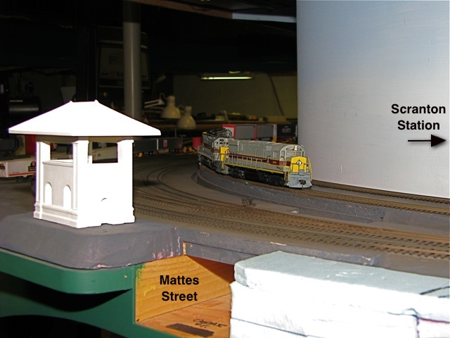 king
king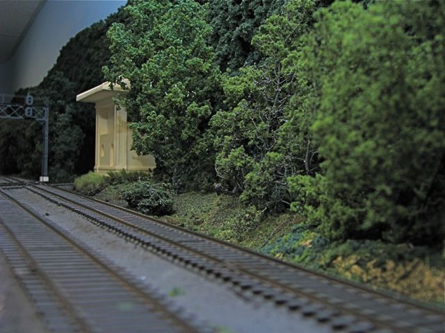
 abo
abo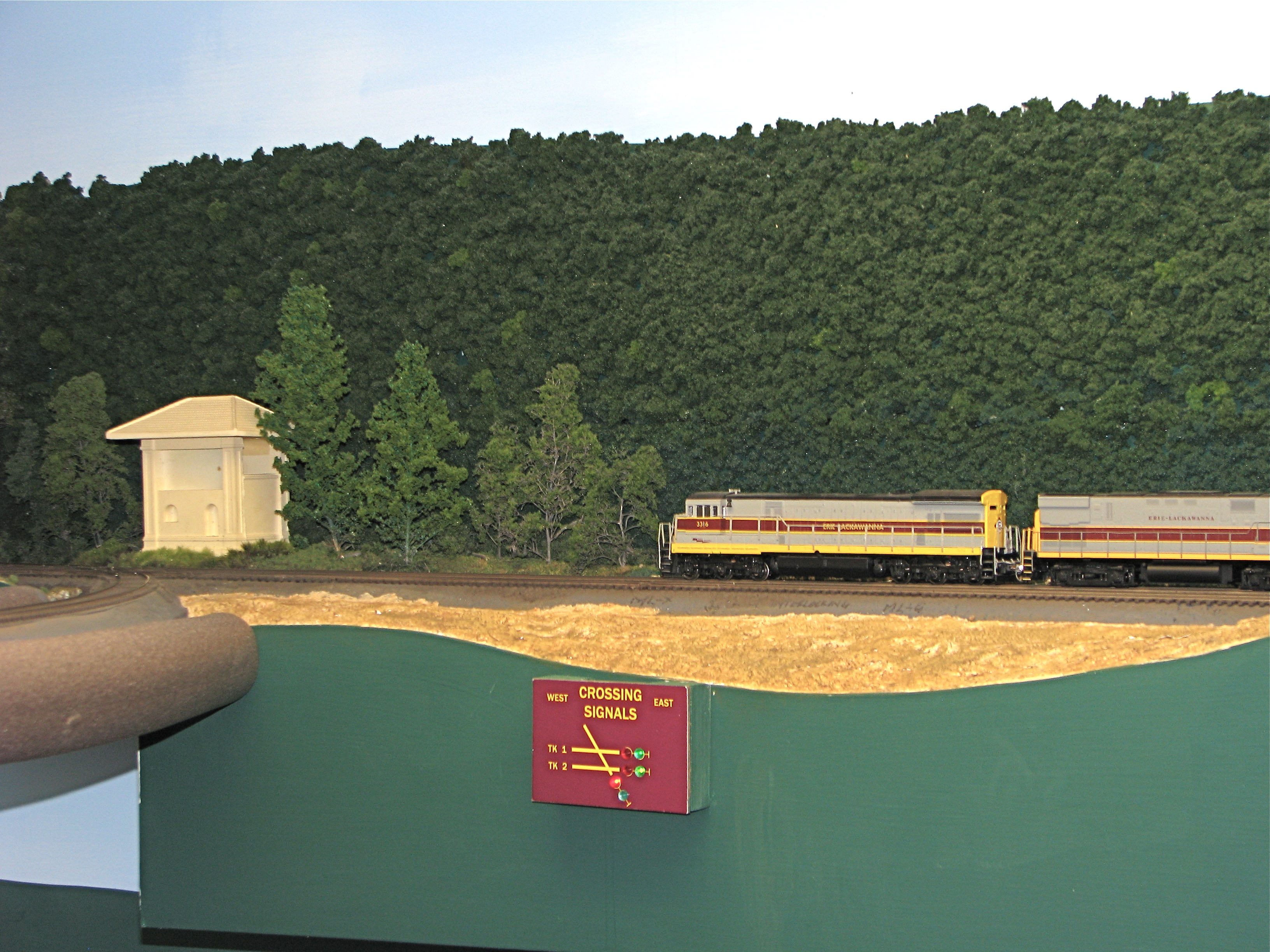 ut the
Internet in 2026 I find no references to the The Hobby Gallery Lackawanna tower models. But I did come across
images of what seems to be the plaster Hobby Gallery Lackawanna tower models
on Jeff Mutters's very impressive layout. The models appear in an unfinished plaster window-less state,
and judging on what an ordeal its was for me to put them together,
I am not surprised they are unfinished in the photos.
ut the
Internet in 2026 I find no references to the The Hobby Gallery Lackawanna tower models. But I did come across
images of what seems to be the plaster Hobby Gallery Lackawanna tower models
on Jeff Mutters's very impressive layout. The models appear in an unfinished plaster window-less state,
and judging on what an ordeal its was for me to put them together,
I am not surprised they are unfinished in the photos.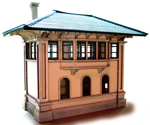 026, I see that another firm "The N Scale A
 rchitect" offers nice looking model Lackawanna Railroad concrete
towers made from laser cut fiberboard. They offer both the
smaller and larger version of the Lackawanna Railroad concrete towers in laser cut fiberboard.
The model on the left is the larger wider version of a
Lackawanna Railroad concrete towers and is available in HO scale.
rchitect" offers nice looking model Lackawanna Railroad concrete
towers made from laser cut fiberboard. They offer both the
smaller and larger version of the Lackawanna Railroad concrete towers in laser cut fiberboard.
The model on the left is the larger wider version of a
Lackawanna Railroad concrete towers and is available in HO scale. 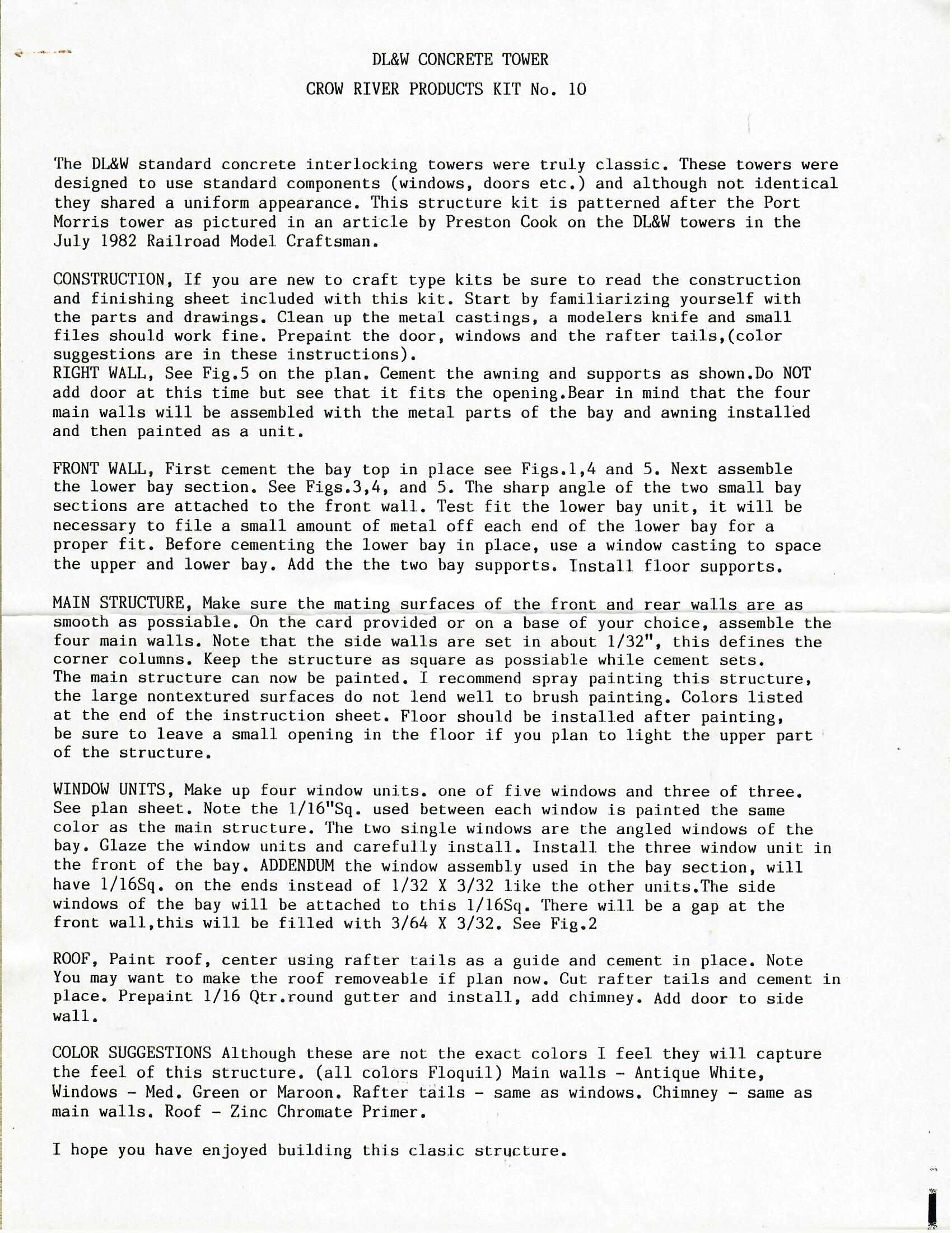
 n th
n th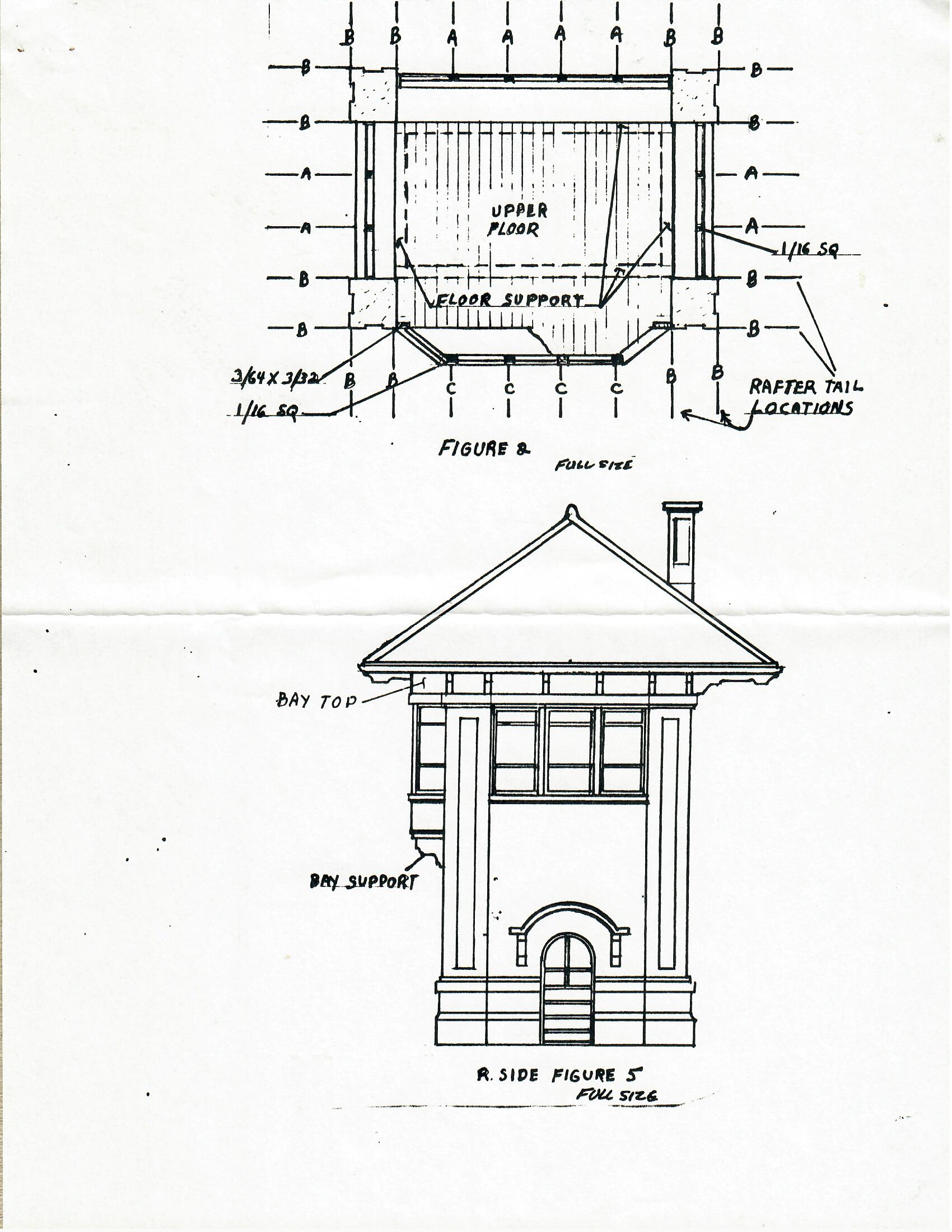 e
summer
e
summer of 2026 I
got up enough nerve to try to tackle this
seemingly difficult plaster model kit. I started by a
thorough study the images that came with
the structures. Here is the entirety of the paperwork that
came with the kits.
of 2026 I
got up enough nerve to try to tackle this
seemingly difficult plaster model kit. I started by a
thorough study the images that came with
the structures. Here is the entirety of the paperwork that
came with the kits. 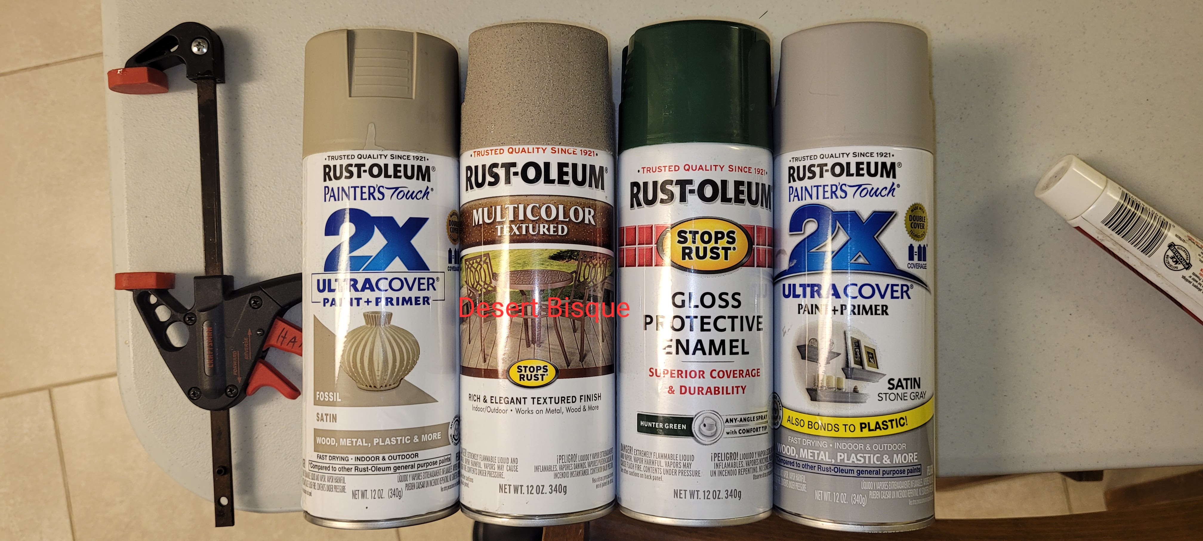
 nts that I
used were:
nts that I
used were: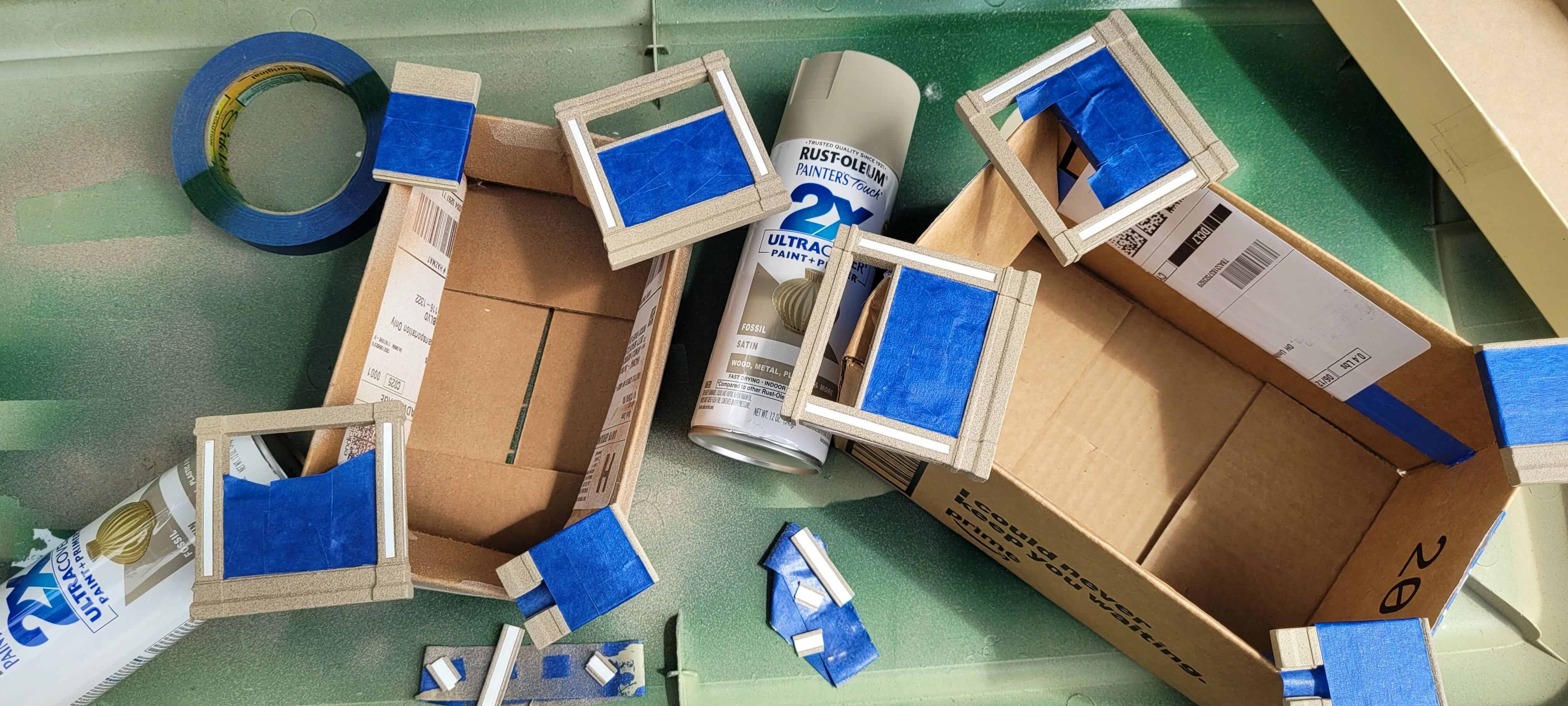
 ded
to be glued with 90 degree
angles between them.
The plaster castings had no
reference points to do
so. So I made another
jig out of Lego. The
jig was wrapped in a bit of
tape to bring it up to the
right dimensions and greased
with plumbers lubricant so
the glue would not adhere to
the jig. I used plain
white Elmer's glue and
gently clamped the walls to
the jig. I was careful
to inset the side walls
1/32" which "defined the
corner columns" as stated in
the
instructions.
ded
to be glued with 90 degree
angles between them.
The plaster castings had no
reference points to do
so. So I made another
jig out of Lego. The
jig was wrapped in a bit of
tape to bring it up to the
right dimensions and greased
with plumbers lubricant so
the glue would not adhere to
the jig. I used plain
white Elmer's glue and
gently clamped the walls to
the jig. I was careful
to inset the side walls
1/32" which "defined the
corner columns" as stated in
the
instructions.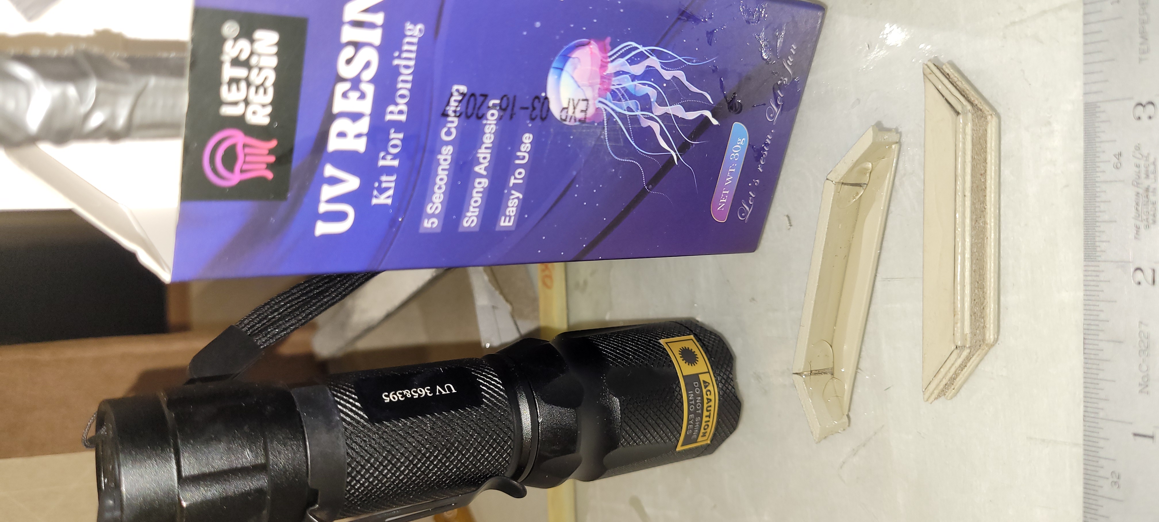

 I decided to make sturdy bases for the
towers. One tower is destined to be a desk display item, the
other tower will be a layout structure.
I decided to make sturdy bases for the
towers. One tower is destined to be a desk display item, the
other tower will be a layout structure.