Once you have
entered the server lists, save your ATCS file again ("my atcs map"
or whatever you fancy). Exit and relaunch ATCS Monitor and
reload your "my atcs map.ini" file. If you did this
correctly, after a short time,
data
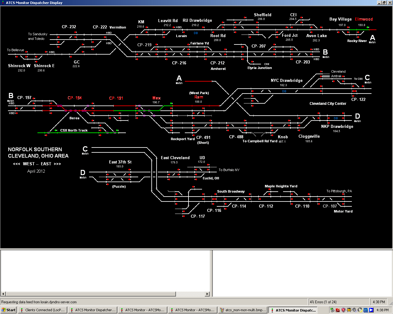
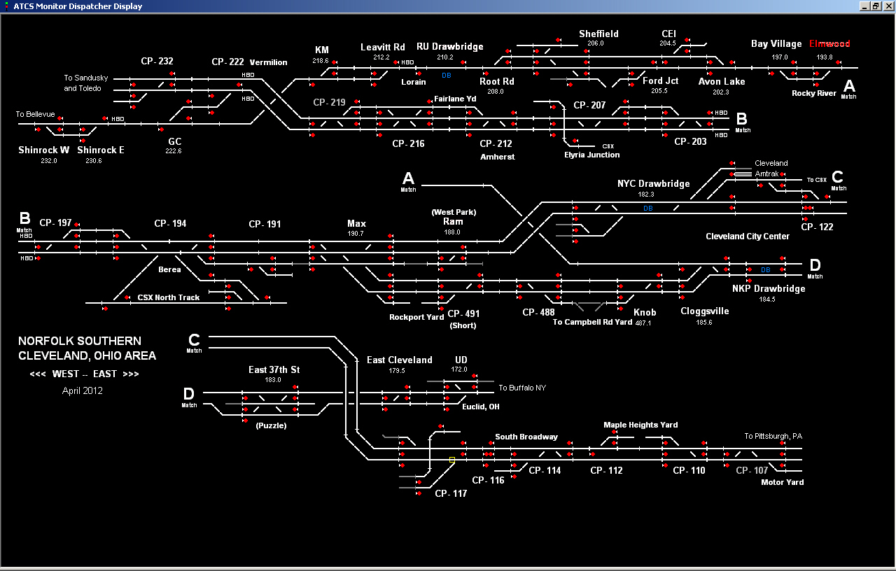
will be scrolling down the screen, and if you click on
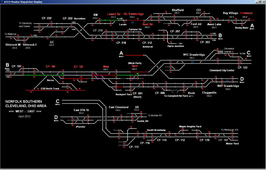
"Dispatcher Display", you should see
something
like
this. Control Point signals are either cleared (green)
or red. White lines are track, Green lines are tracks lined
up for trains, red lines are tracks with trains on them, small
squares on turnouts are an indication of turnout
repositioning.
Red Control Point labels are actively receiving
ATCS data. White Control Point labels are not receiving any
ATCS data, almost always because the data is not being captured
and re-broadcast by any local railfans. On the above map,
only 5 of about 35 Control Points are picking up ATCS data, (the
lonely Elmwood one being my contribution to the effort). In
time, more ATCS Monitor servers may come on line and more
un-monitored white Control Points will become red ones.
Now that we did so much work, save this file
with a file name, something like "my atcs map internet.ini" from
earlier
Let's
watch the trains on the map via radio scanner input (no
internet feed at this time)
For this example we need to tell
the ATCS program that the data stream is coming from our scanner
radio instead of the internet. Remember:
The
data can come from an Internet connection, or from the scanner
radio. To use both sources simultaneously, the scanner
radio data input has to be set to a server and then fed to the
Internet connection (two instances of ATCS Monitor will need to
run at the same time to do that), more about that later.
Hopefully the scanner is hooked up to the
computer via the instructions from
earlier in this document. Don't forget to turn the
scanner on, and have the right frequency dialed in.
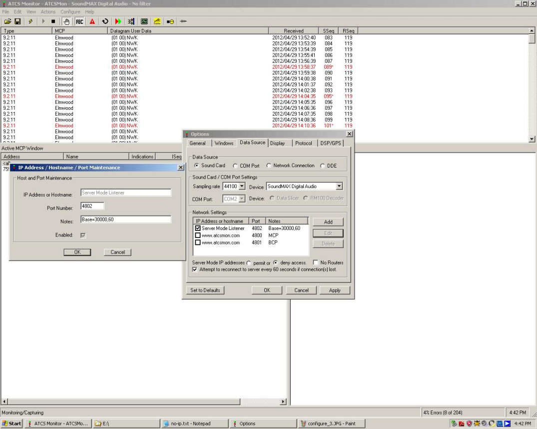
Load your recently made file
"my atcs map.ini" . Go to the "Options" tab again, click it,
and then the "Data Source" tab. Click on the "
Sound
Card" button. Notice that of the four possible Data
Sources only one can be used at a time and . Here we clicked
on "
Sound
Card" and some of the stuff on the menu box gets grayed
out. In the "Device" box, a short listing of things that the
computer recognizes as sound cards will be shown. In my
case, we see a "SoundMAX Digital Audio" entry for my sound
card. If I were to use a Griffin I-Mic USB sound card, the
I-Mic would be listed as a choice in this box. The "Sampling
Rate" box shows 44100 automatically and I left that alone.
The "COM Port" box is grayed out. I
unchecked the box marked "No
Routers" and this allows people with aggregate ATCS Monitor
servers to feed off my ATCS Monitor server.
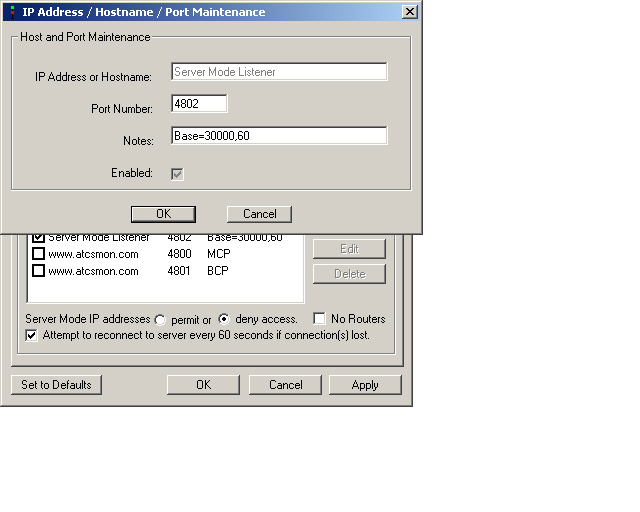
In the big "Network Settings" box, I put a
check next to "Server Mode Listener" and used the
Edit
button to give "Server Mode Listener" a TCP port a value of 4802
(I have seen other ATCS servers with TCP port values ranging from
4799 to 4900 and many values between. I would recommend
picking a TCP port number between 4799 and 4900 but would perhaps
avoid TCP ports 4840, 4843, 4847, 4894, 4899 as these may be
reserved for specific purposes.). And I also entered a
"Base" of 30000,60 which sets up my UDP ports. By
specifying 30000,60 I am basically specifying sixty UDP
ports will be available, from 30000 to 30059.
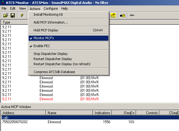
Then check the
"Actions"
button
and then "Monitor MCP's" begin monitoring the MCP's.
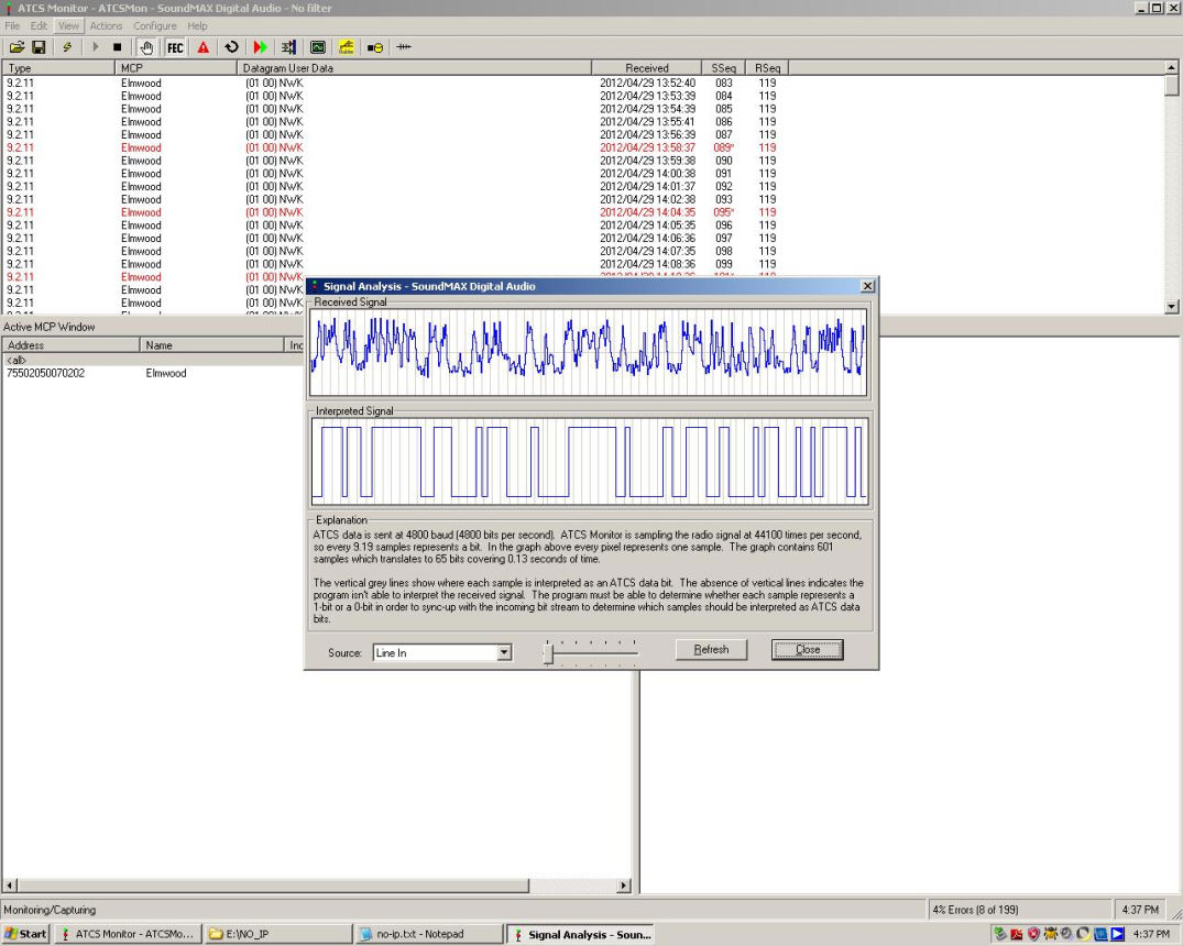
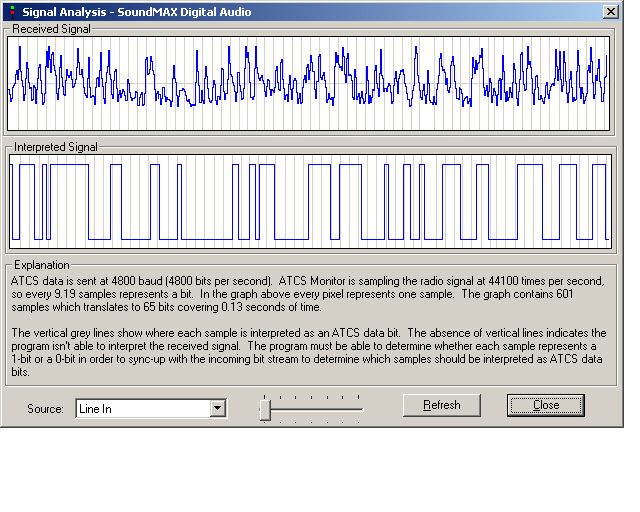
To see if your radio scanner is indeed transmitting anything at
all to your sound card, check the "
Signal
Analysis" by clicking "View" and then click on "Signal
Analysis". With "Signal Analysis", you should
see
something like this. If the box has only a flat line,
then the scanner and the sound card are not communicating.
If you see a wavy line like in this "Signal Analysis" example,
that is good. That is the background radio static that we
see between the occasional bursts of ATCS transmissions.
Note the little slider bar on the bottom. Move it back and
forth till the wavy line is almost touching the top and bottom of
the "Signal Analysis" box. The wavy line should not be
hitting the top or bottom of the box, that will clip the signal,
and the wavy line should not be to small in relation to the
"Signal Analysis" box. In this case, the slider is almost
all the way to the left. On other computers, or if I use a
Griffin I-Mic, I find the slider is usually sort of in the middle
of its left-right range.
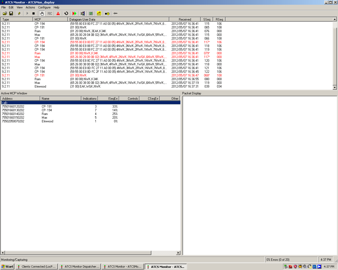
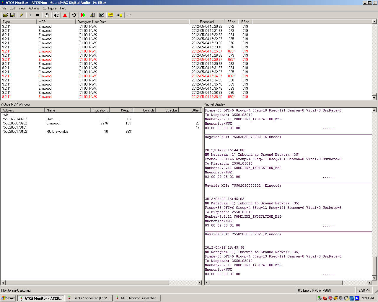
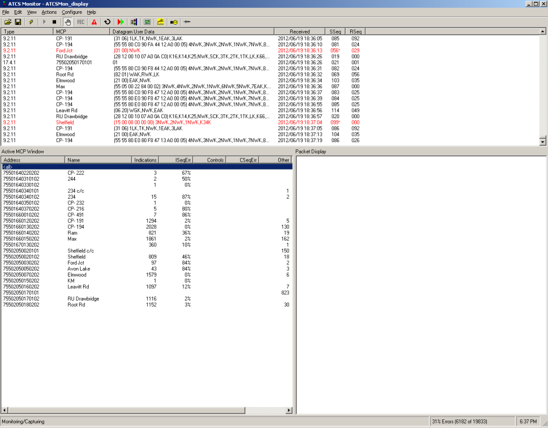
Here is
what the ATCS
Monitor shows when feeding only from the radio scanner.
Note that the data is flowing mostly from the only MCP that is
close enough to me to reliably receive, "
Elmwood",
thus
only Elmwood is displayed in red letters. After five days of
data collection a few other Control Points such as "RAM" and "RU
drawbridge" and an unknown MCP have contributed a few (17) blips
of data compared to the 7276 blips of data from the nearby
"Elmwood" Control Point.
Here are more screen shots of the ATCS Monitor
settings, since they work for me, they may be of help to readers
of this page:
Configure
Options
General Note that I put a check in the "Ignore
Decoding Errors" box.
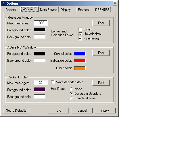
Configure
Options
Windows (ATCS)
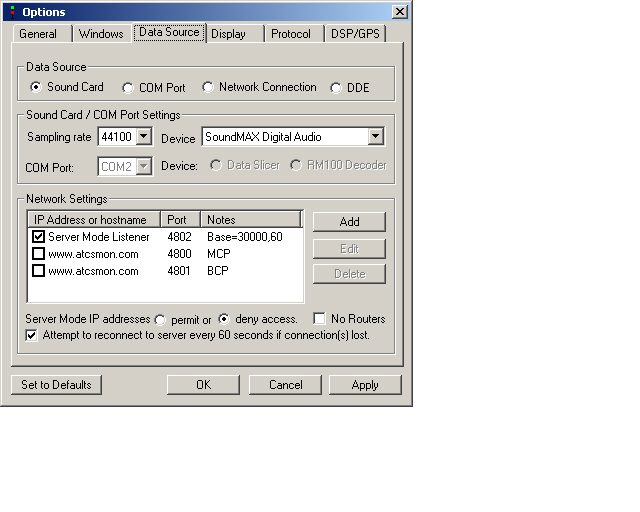
Configure
Options
Data Source
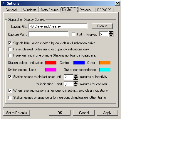
Configure
Options
Display
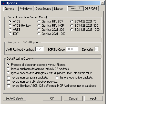
Configure
Options
Protocol
Configure
Options
DSP/GPS
Configure
Railroad
Information
Configure
Rules
Save these settings with a unique file name,
something like "my atcs map scanner.ini"
Ports, TCP and UDP
What are
TCP
and
UDP ports anyway? A home computer connected to the
internet needs TCP ports so that certain computer programs can
communicate to and fro with the internet. Port 25 is
reserved for SMTP E-mail protocols. Port 80 is reserved for
an internet web server, port 110 is reserved for POP3 Post
Office Protocols for E-mail. For ATCS Monti tor, I see that
the TCP ports between 4799 and 4900 (avoiding TCP ports 4840,
4843, 4847, 4894, 4899) are often used for allowing ATCS Monti tor
to communicate with the outside world.
If you pick a TCP port, (I used
4802) that specific port must be opened in your
network (DSL or
Cable) router-switch configuration, (more on that
later). ATCS Monitor data coming to and from the internet
get funneled to the particular computer on a home network that has
the TCP port specified (4802 in my case) and the ATCS Monitor
program is instructed by the Configuration to use that port.
Basically, the TCP port is making a doorway or a data pathway that
links ATCS Monitor program on you computer with the internet
world.
The UDP ports are chosen as multiple slots in
your hosting computer that can be filled by visitors from the
outside world, sort of like seats in a theater. If you set
up an ATCS Monitor server and collect local information from your
radio scanner, other people running ATCS Monitor would most likely
want to partake of this data and thus fill in voids in their ATCS
Monitor maps. By setting up UDP ports, you can specify how
many visitors or seats in you theater you will permit. And
by setting this up, the seats can be defined in a small area (a
limited number of UDP ports) instead of spread out all over the
UDP port world on your computer.
I figured sixty ATCS Monitor visitors or seats
would be a good start, perhaps I'll need more UDP ports at a later
date. So, I set up the UDP ports for sixty ATCS Monitor
visitors (
Base=30000,60)
which means I have made UDP ports 30000 through 30059 available
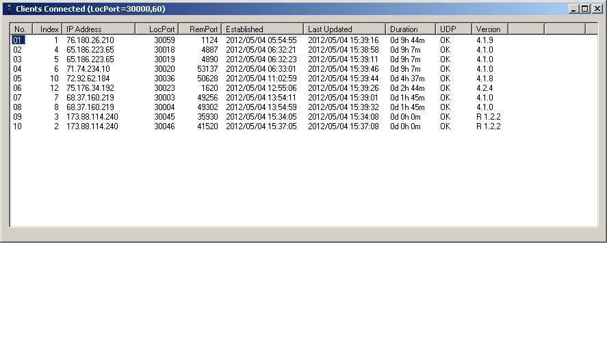
for ATCS Monitor visitors. Till now, the most visitors I
have ever seen is about 16. The visitors can be seen on the
Clients
Connected window of ATCS Monitor, some are duplicates,
indicating that they are perhaps unwittingly running more than one
instance of ATCS Monitor.
Just like the TCP ports, the UDP ports must be
enabled in your network (DSL or Cable) router-switch
configuration, (more on that later). And when doing that,
the router-switch will need to be told which particular computer
is running ATCS Monitor on your home network. And that
router-switch will need to make the TCP and UDP ports enabled for
ATCS Monitor directed towards that particular computer.
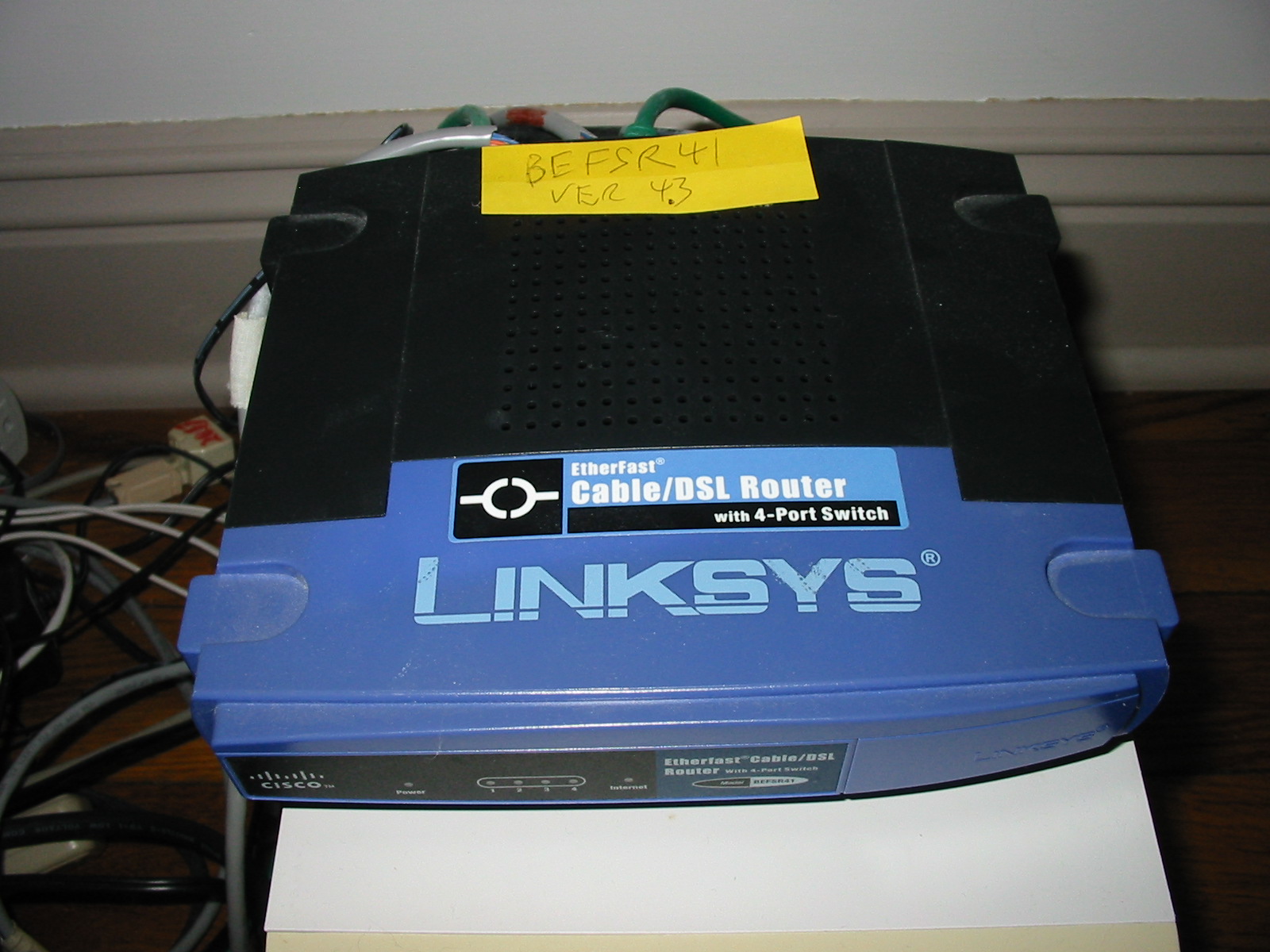
(DSL or Cable)
Router-Switch Configuration
If you are using more than one computer on a
home network, then you likely are using a
network (DSL
or Cable) router-switch. In my case, I have an
old computer with only one
mission, to run as an ATCS Monitor server. This computer is
on my home network where several other computers are used for day
to day things like e-mail, Internet surfing, business stuff,
gaming, banking, etc.
Do your self a favor,
assign STATIC
Local
Area Network (LAN) addresses for your computers on your
network, or at least for the computer that is the ATCS Monitor
server . Why? If you do not, then your (DSL
or Cable) router-switch will use its built in Dynamic Host
Configuration Protocol (DHCP) and give the computers their own
(LAN) addresses, and these can change depending upon the sequence
of which computers are turned on when. For example, the (DSL
or Cable) router-switch on my network is a Linksys E 1200, and by
design, this (DSL or Cable) router-switch itself will always
be at LAN address 192.168.1.1 But, the
computers on the LAN can have LAN addresses from 192.168.1.
2 through 192.168.1.
255
So, if I turn on computer A, then computer B,
and then computer C, and the (DSL or Cable) router-switch's
DHCP is at its "enabled" setting, the computer LAN addresses will
likely be:
computer A= 192.168.1.2
computer B= 192.168.1.3
computer C= 192.168.1.4
But if I turn the computers on in a different sequence, say
computer C, then computer B, and then computer A, and the (DSL or
Cable) router-switch's DHCP is at its "enabled" setting, the
computers LAN addresses will likely be different, such as:
computer A= 192.168.1.4
computer B= 192.168.1.3
computer C= 192.168.1.2
For our computer that is acting as an ACTS
Monitor server, we want a LAN address that does not change over
time, otherwise it will be harder to configure (DSL or Cable)
router-switch ports that refer to a specific computer at a
specific LAN address.
What to do? Either fully disable the DHCP
feature on your (DSL or Cable) router-switch or set aside a range
of LAN adrress's on your (DSL or Cable) router-switch that are not
subject to change. Here are some web pages that discuss
this:
Static
IP
address setup Converting from a DHCP based LAN
configuration,
Static
and
dhcp at the same time.
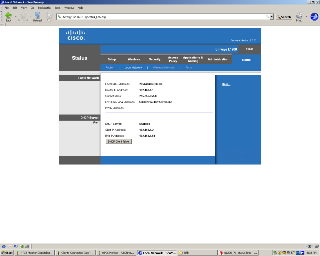
On my system, I have set my LAN address for my
ATCS computer to be 192.168.1.121 and on my Linksys (DSL or Cable)
router-switch,
I have these
settings for the DHCP topic. Notice that I have
restricted my LAN automatic enabled DHCP address range from
192.168.1.2 through 192.168.1.51 Since my ATCS
Monitor computer is at 192.168.1.121, the ATCS computer will fall
outside the range of the above, my ATCS computer will be in the
area that static LAN addresses can be used, i.e, 192.168.1.52
though 192.168.1.255
I left the "Subnet Mask" settings at the
default 255.255.255.0 and set my "Keep Alive Period" to 180
seconds.
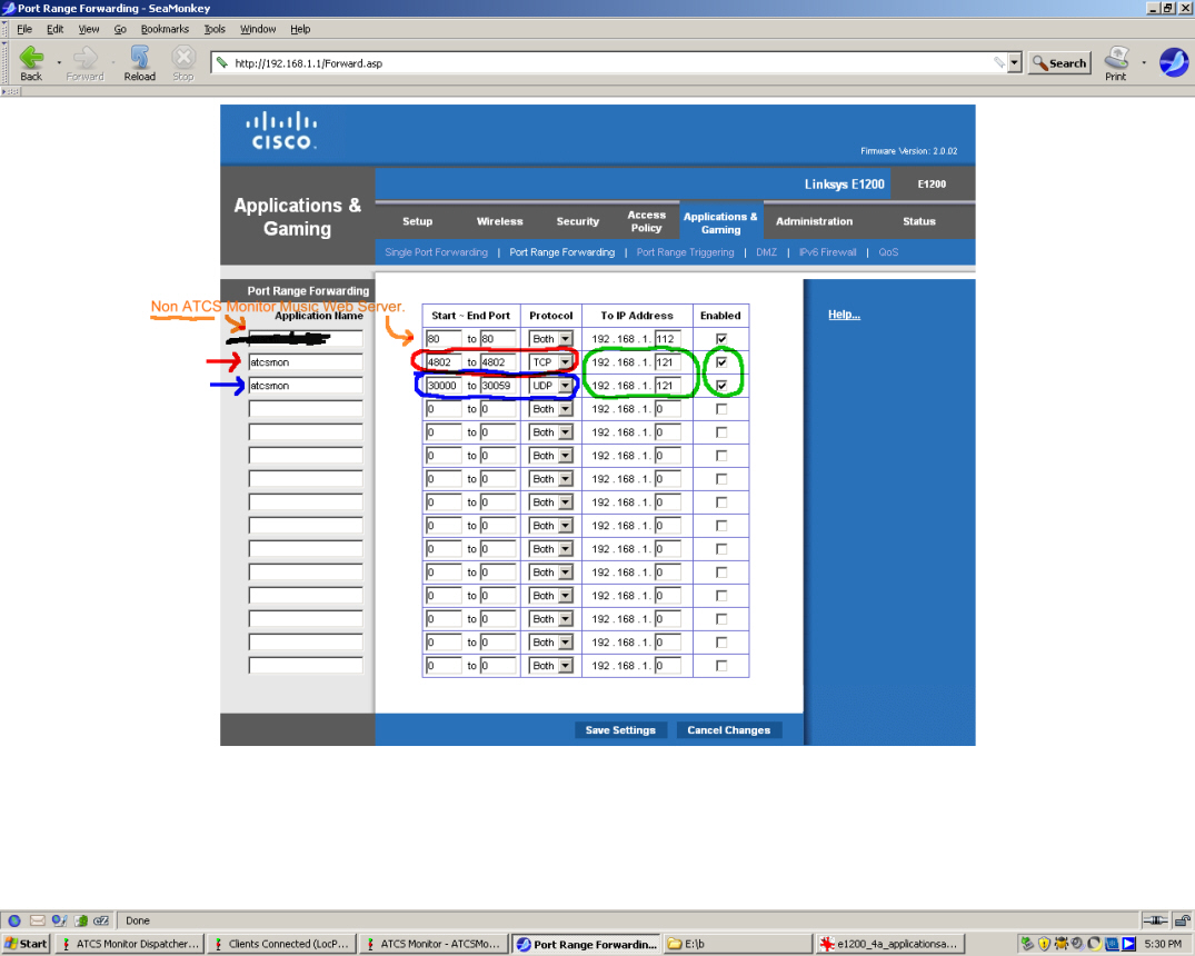
While we are setting up the (DSL or Cable)
router-switch settings, we might as well open up TCP and UDP ports
that will be needed for the ATCS Monitor server to communicate
through your LAN to the outside world's Internet. I set up
TCP
and
UDP ports here, where the red arrow row shows the TCP ports
being set up 4800 though 4802 (I only am using 4802 now) and the
blue arrow shows the sixty UDP ports being set up, 30000 through
30059. Now, look at what was circled in green. Enter your
LAN address of the computer running ATCS Monitor (mine is
192.168.1.212 ). Be sure to put a check mark in the boxes on
the right side of the column, or your settings will not take
place.
Another DSL or Cable) router-switch setting
that is optional, but I changed allows certain ports and
applications to have high or low priority.
Surprisingly, on
another
part and
another
part of the (DSL or Cable) router-switch settings area, I
did
not have to
make any changes nor entries for my ATCS Monitor server.
This page can be left at the default values. Note that
another computer at 192.168.1.112 is an "HTTP" server for a music
web page, and has a port setting of 80. That computer
192.168.1.112, is completely unrelated to ATCS Monitor.
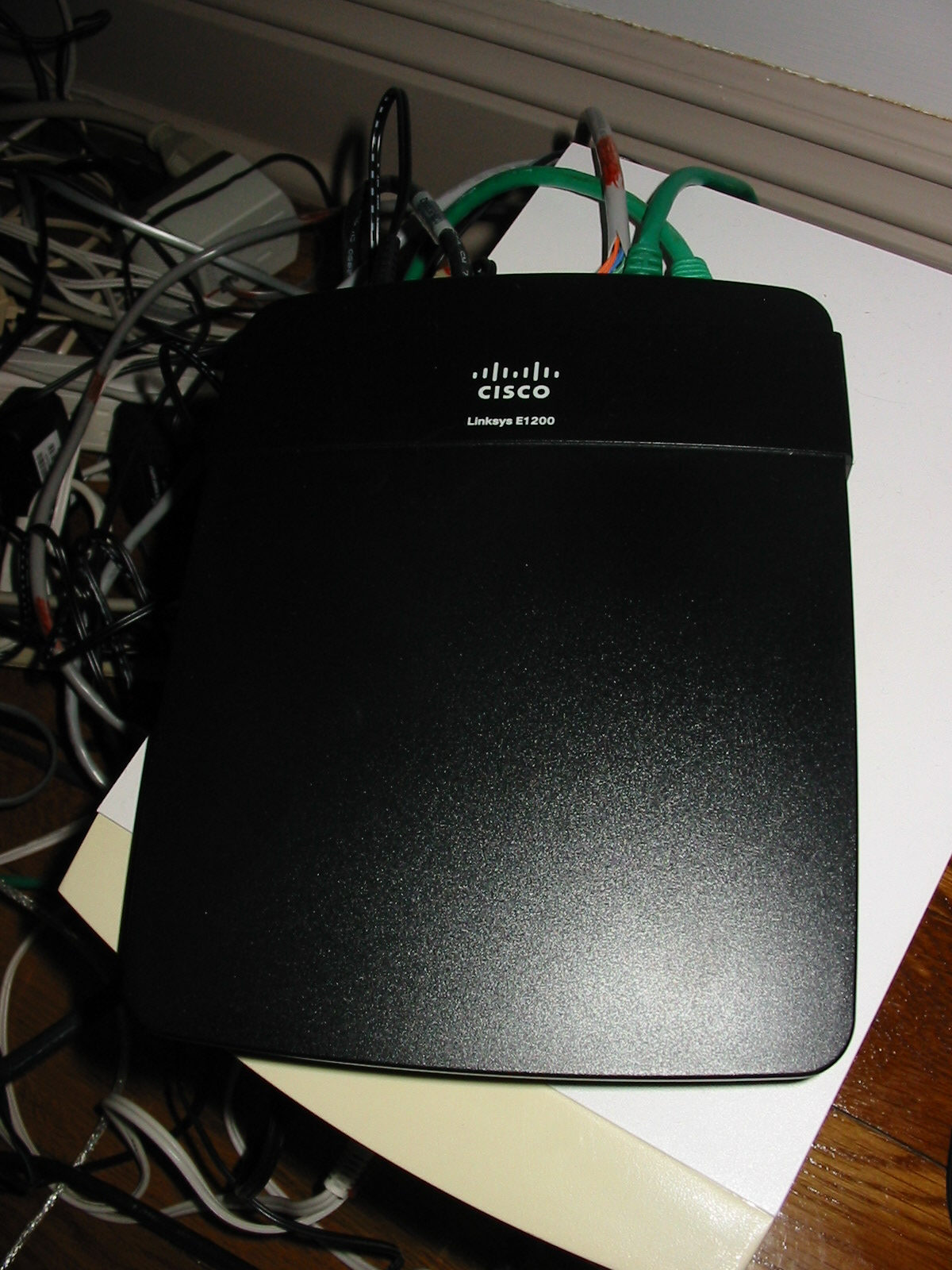
Since my DSL or Cable router-switch settings
seem to work, I'll share them here for what it is worth.
Here is a complete series of snapshots of my
Linksys E 1200 DSL or Cable
router-switch settings, remember my computer that is running the
ATCS Monitor is at LAN address 192.168.1.121 :
Linksys_Setup-Basic_Setup
We made changes here.
Linksys
Setup-IP
V6 Setup
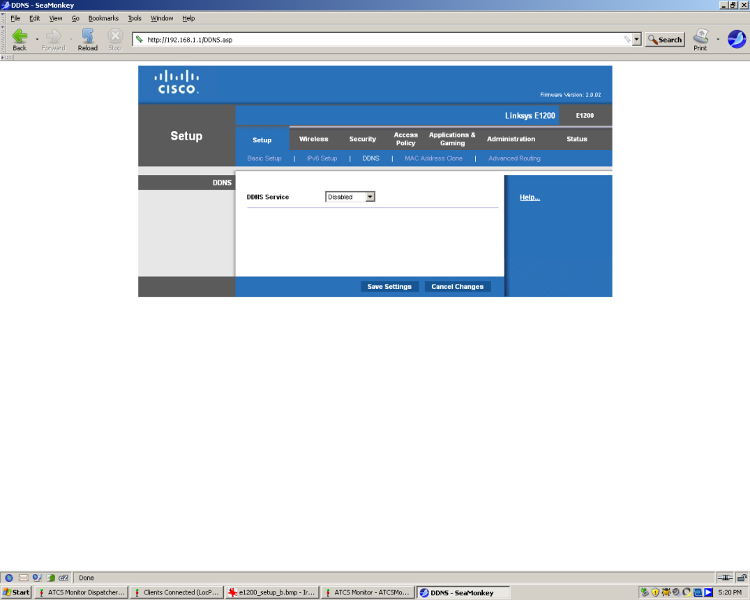
Linksys_Setup-DDNS
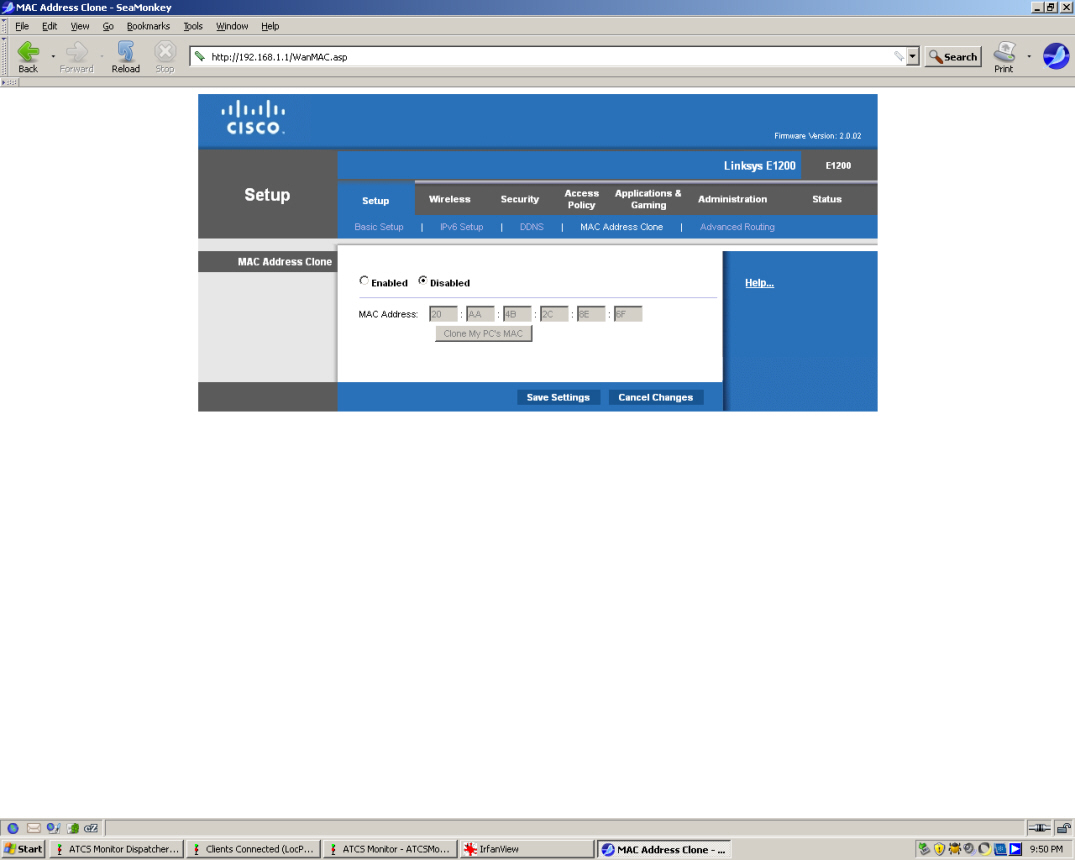
Linksys_Setup-MAC
Address
Clone
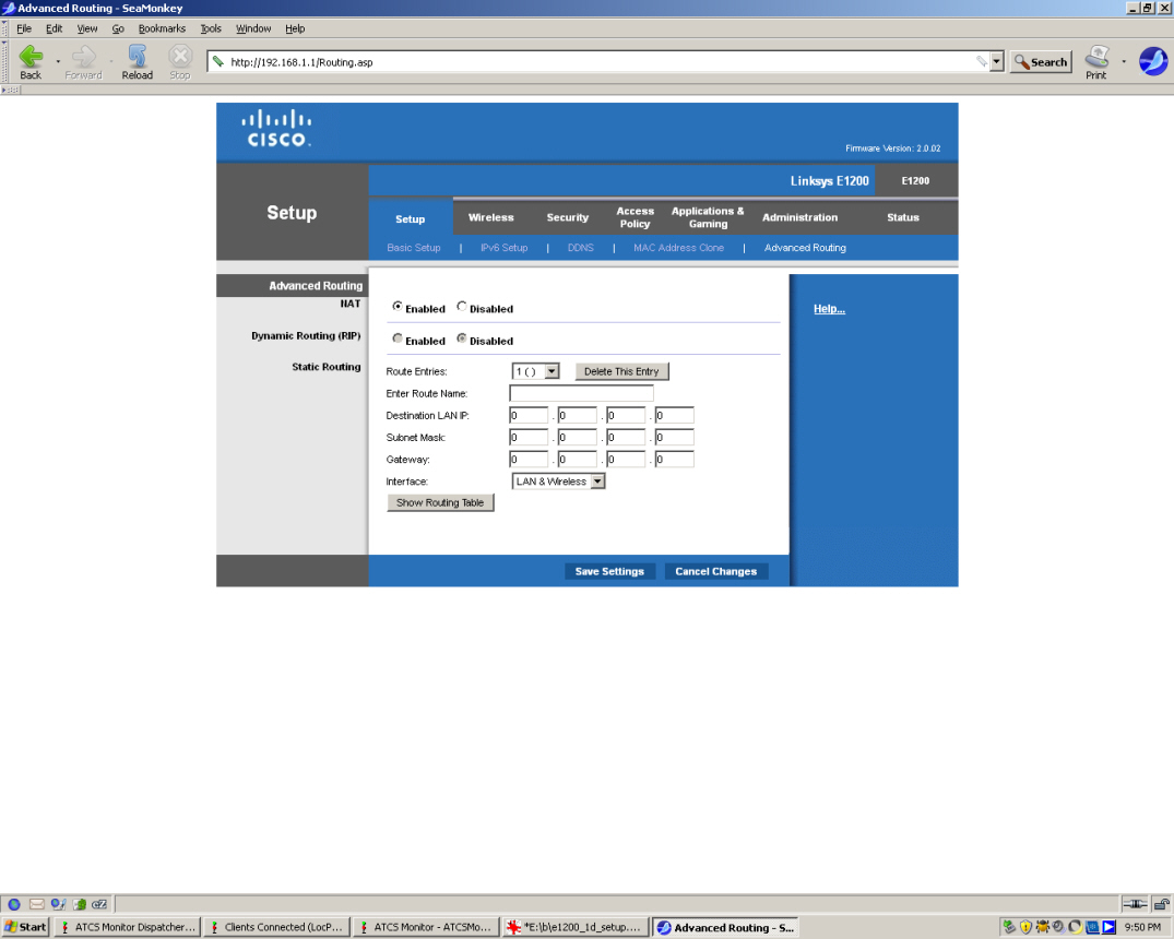
Linksys_Setup-Advanced_Routing
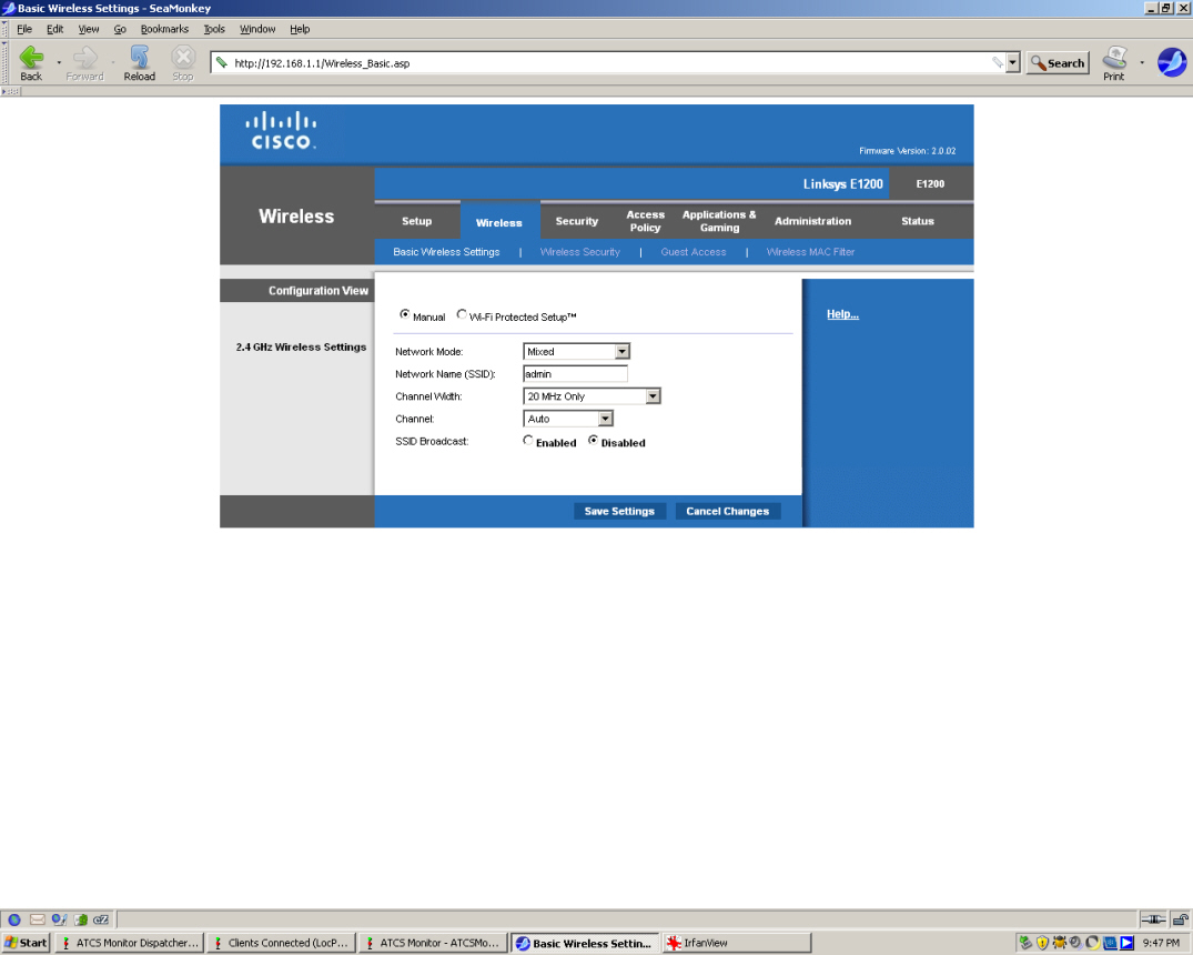
Linksys_Wireless-Basic
Wireless
Settings
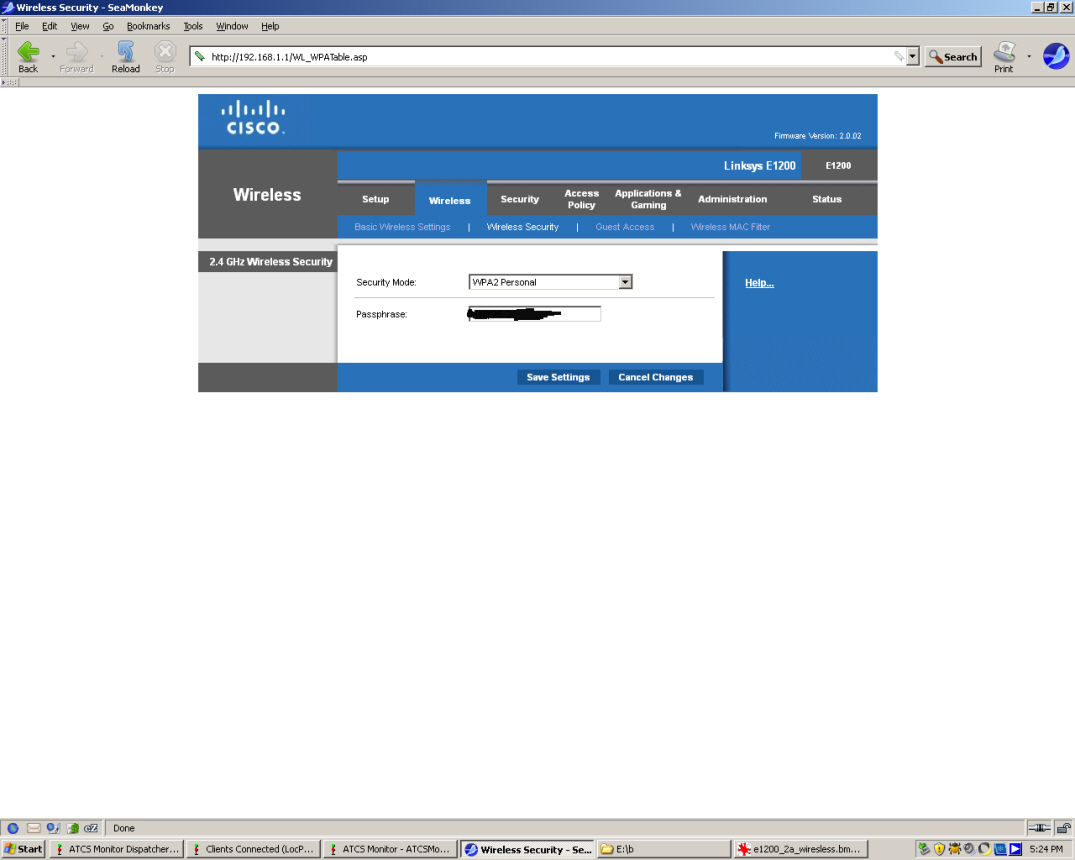
Linksys_Wireless-Security
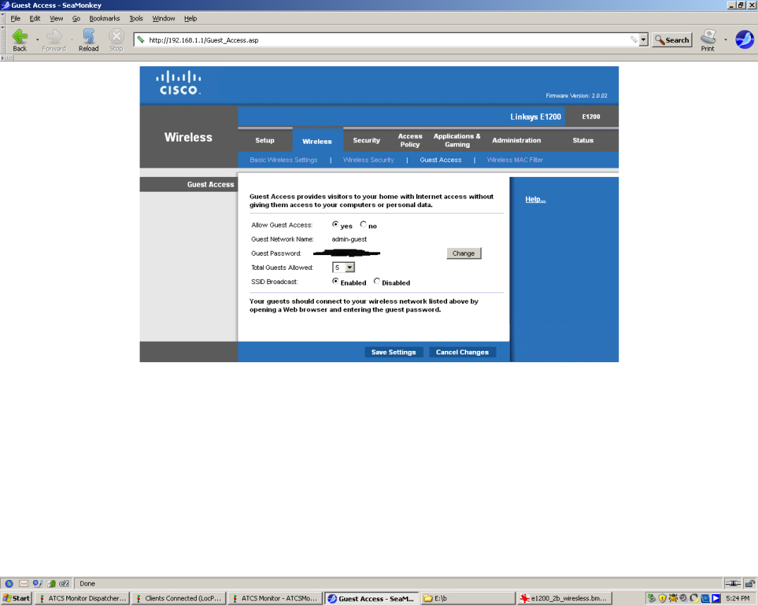
Linksys_Wireless-Guest
Access
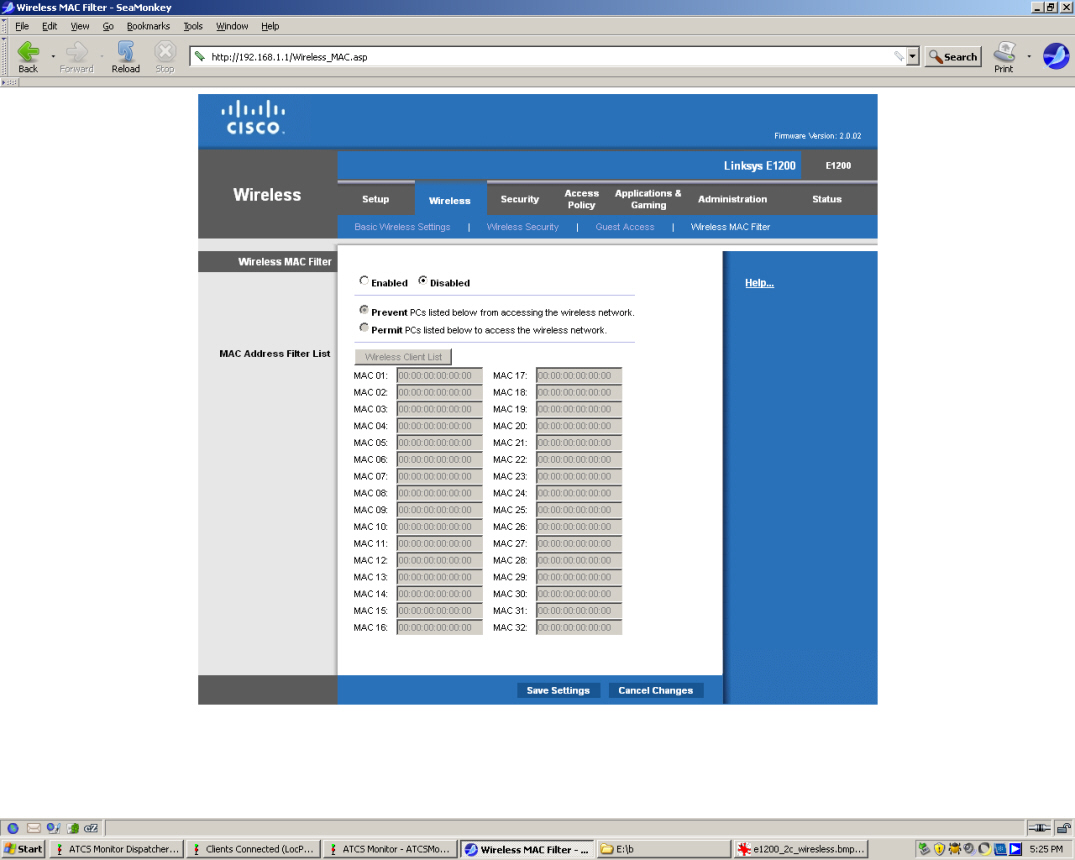
Linksys
Wireless-MAC
Filter
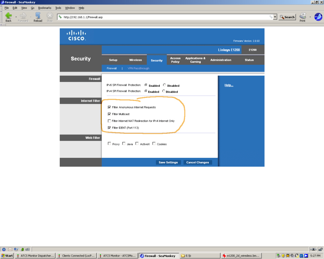
Linksys_Security-Firewall
I
made changes here, but these changes don't really pertain to ATCS
Monitor.
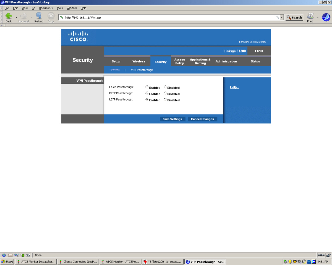
Linksys_Security-VPN
Passthrough
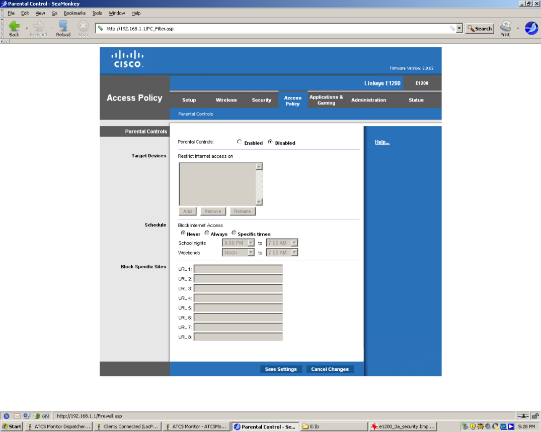
Linksys_Access
Policy
Linksys_Applications
Gaming-Single
Port Forwarding
Linksys_Applications
Gaming-Port
Range
Forwarding We made necessary changes here.
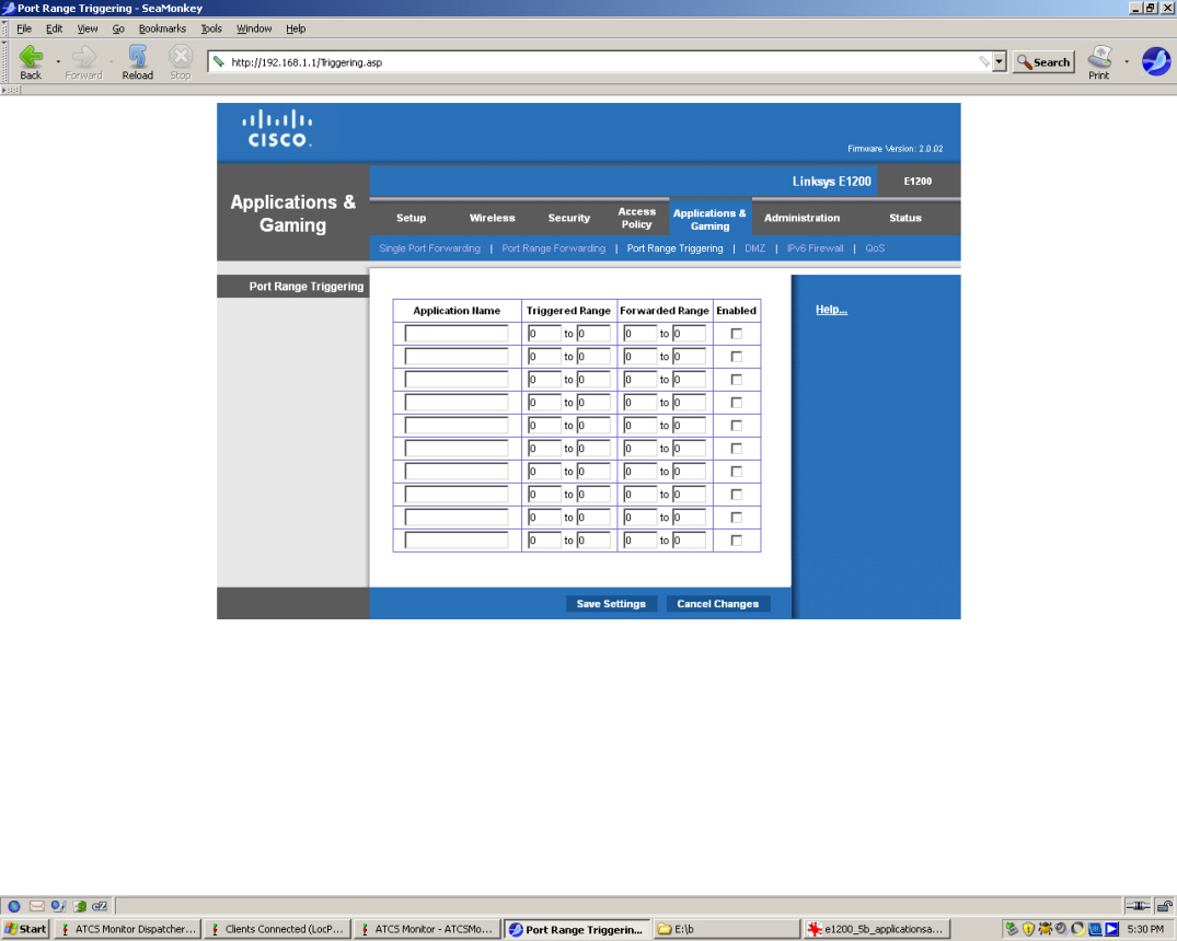
Linksys_Applications
Gaming-Port
Range Triggering
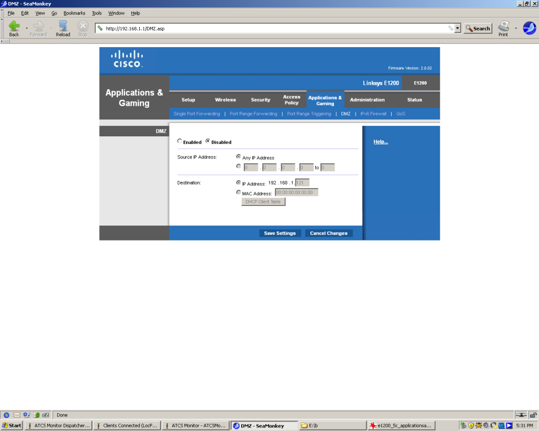
Linksys_Applications
Gaming-DMZ
Linksys_Applications
Gaming-IPv6
Firewall
Linksys_Applications
Gaming-QoS
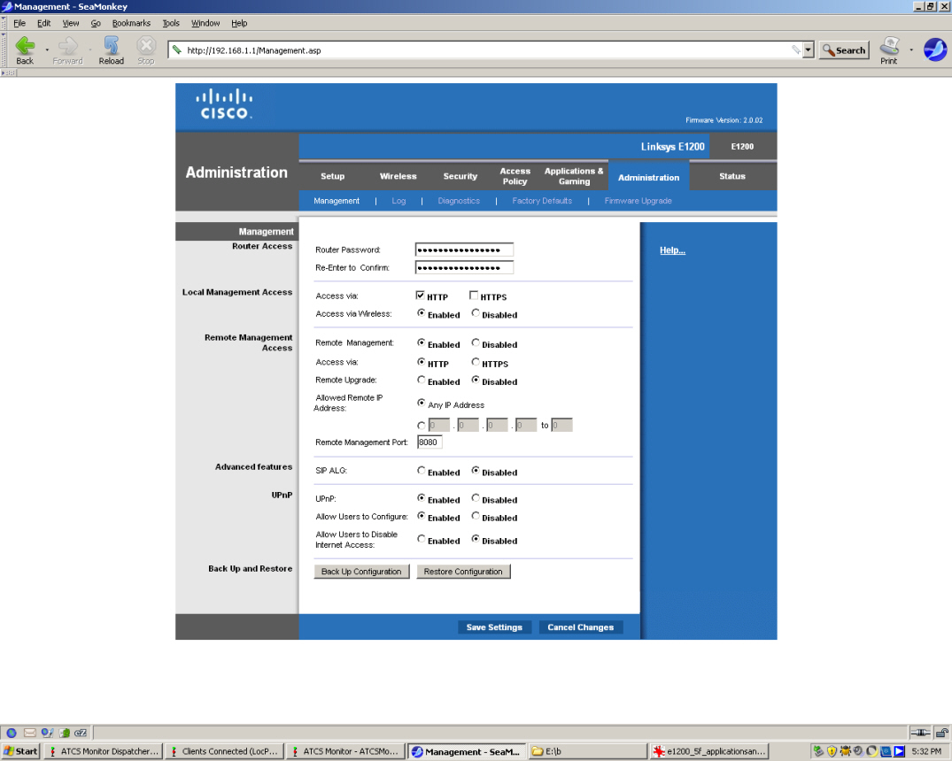
Linksys_Administartion-Mangament
Linksys_Administration-Log
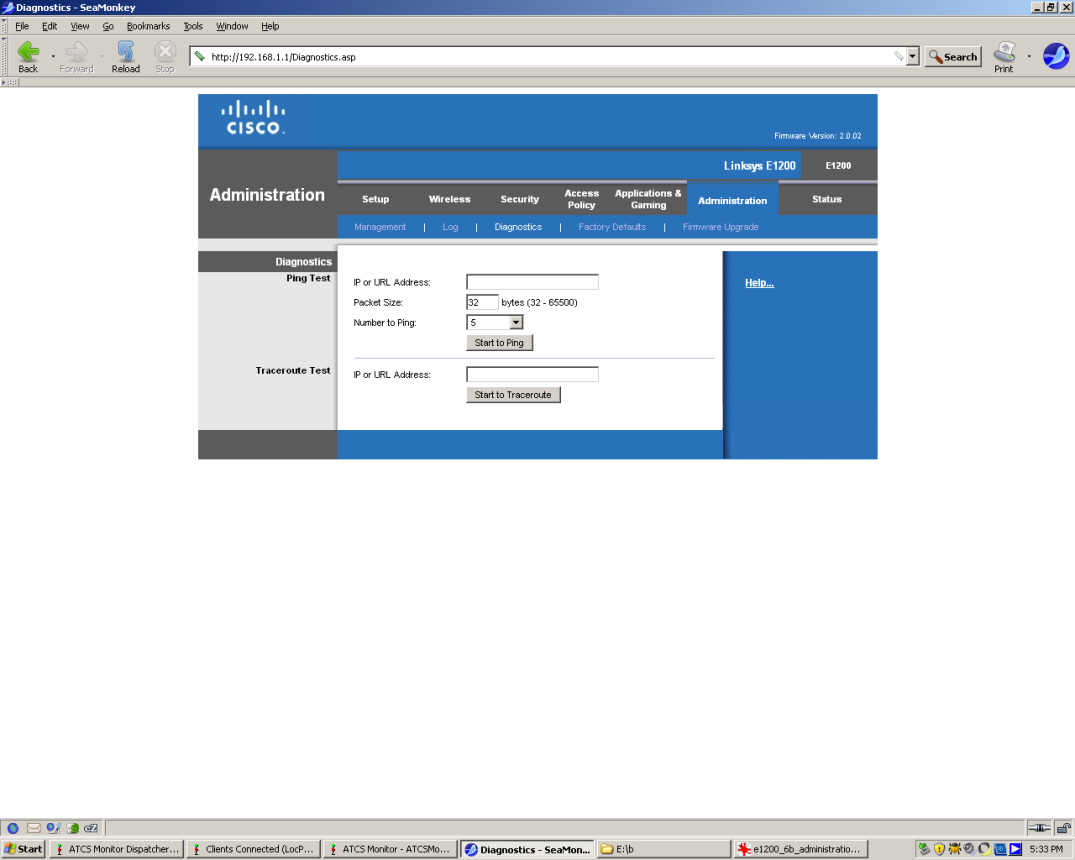
Linksys_Administration-Diagnostics
Linksys_Administration-Factory
Defaults
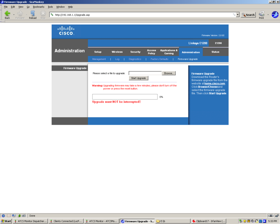
Linksys_Administration-Firmware
Uprgrade
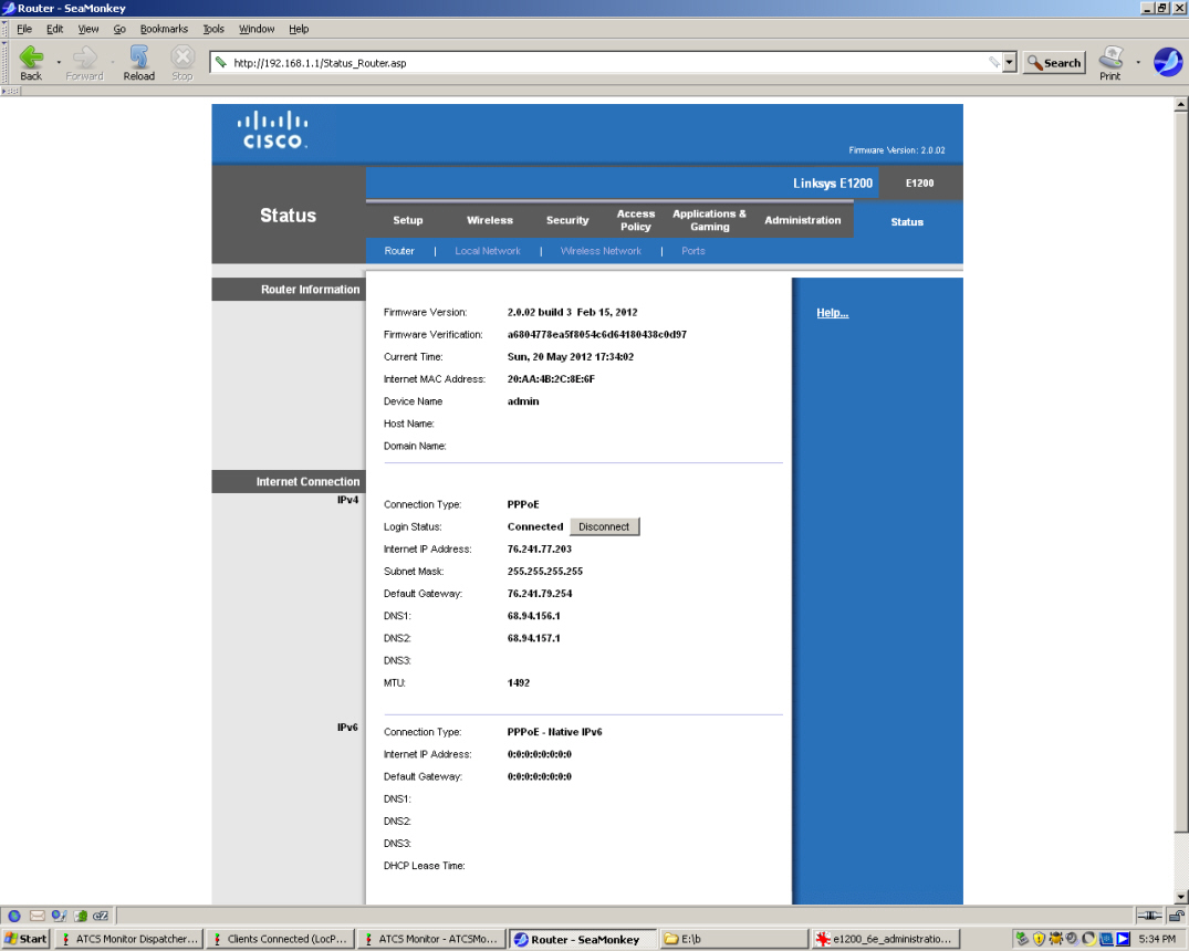
Linksys_Status-Router
Linksys_Status-Local
Network
Linksys_Status-Wireless
Network
Linksys_Status-Ports
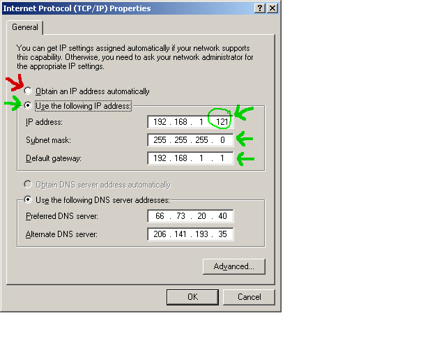
How
to set the Local Area Network (LAN) address on your ATCS
Monitor computer
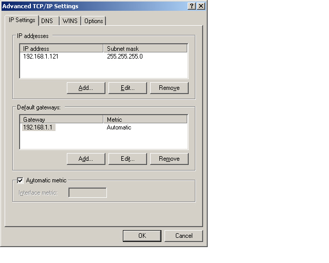
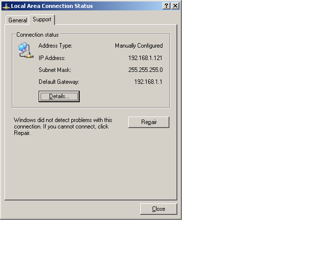
In the above setion, we set aside
Static LAN addresses,
192.168.1.52 though 192.168.1.255 that could be used for an ATCS
computer. My ATCS computer was set at 192.168.1.121 by using
Network Settings in the WinXP Control Panel. This was done
on this
menu, where the green arrows point to the changes I made and
the red arrow points to what was de-selected. Note, my
Linksys (DSL or Cable) router-switch is 192.168.1.1
Here is a complete series of snapshots of my
WinXP network settings on my computer the is running the ATCS
Monitor server:
lan_1status
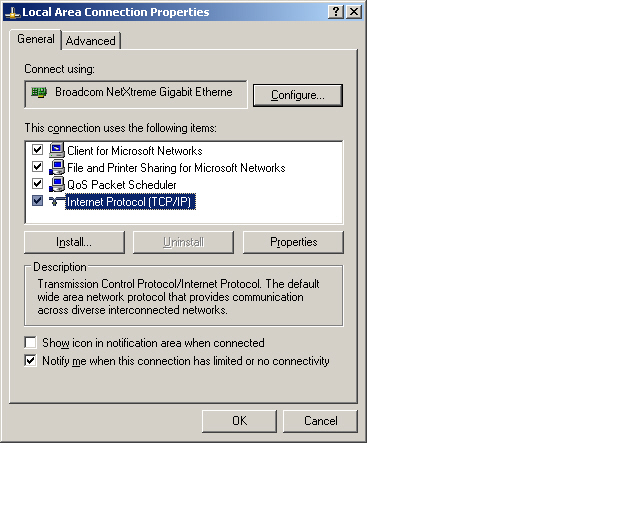
lan_1properties_a
lan_1properties_b
TCP/IP
settings We made changes here.
lan_1properties_b1
IP
settings and Gateway
lan_1properties_b2
DNS
settings
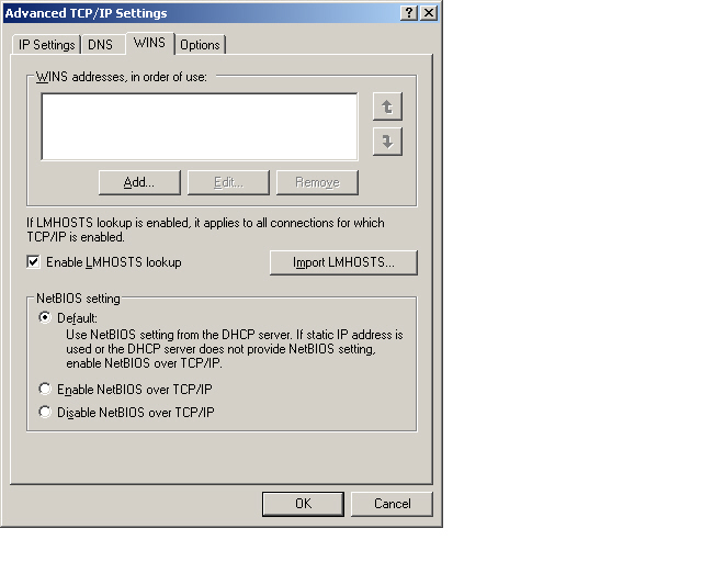
lan_1properties_b3
WINS
lan_1properties_b4
Options
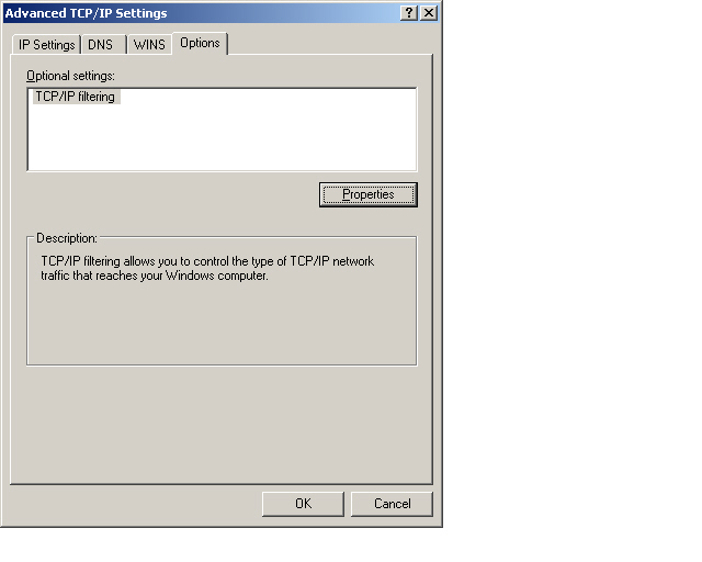
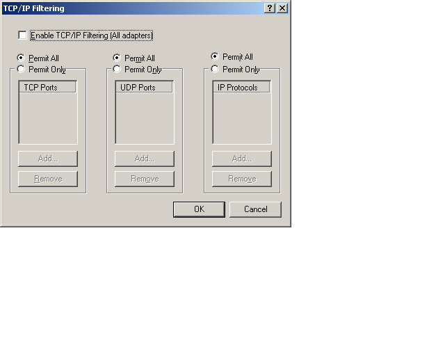
lan_1properties_b4a
TCP/IP
filtering These default settings worked for my TCP
and UDP ports.
lan_2 Support
lan_2 Network
Connection Details
Give
Your
Server an Internet Name so it can Serve the World
By making it to this point, you may be
at stage where you can run ATCS Monitor on a home computer
and you may want to share your local ATCS Monitor with
railfans from the rest of you home town or the whole
world.
If your ATCS Monitor is picking up
valid signals from a radio scanner and you have a
connecton to the internet, you can set up an ATCS
Monitor
server. The type of internet connection does not
seem to really matter, it could be via a T1 line, DSL
(which I have), cable modem, or even a telephone dial-up
modem. Most of us who use the internet at home have
one of the latter three choices.
An interesting thing about home
internet connections is that the internet provider (be it
DSL,
cable modem, or telephone dial-up modem) provides you with
your very own dynamic numerical IP address when you are
connected to the internet. You can check this with
many web sites that can report to you your IP
address. What
is my IP address.com, or IP Location finder.net,
or many others. At the moment, my numerical IP
address assigned by my DSL provider is 76.241.77.203 but
this is not permanent. Everytime you make or
re-establish a connection to the internet, your internet
provider will likely give you a different IP
address. Sometimes, if you have a steady DSL or
Cable modem connection, you IP address may not change for
days or weeks, but sometimes it changes without you
realizing it changed.
Why am I mentioning these changing IP
address that home internet users deal with? If you
want people from the outside world to make contact with
your ATCS Monitor server, they must be provided with an
internet address to your computer running the ATCS
Monitor
server. I could look up my IP address like in the
above paragraph and tell people to enter that into their ATCS
Monitor
program. Since my ATCS
Monitor
server is on port 4802, the IP address that I would give
to the outside world would be 76.241.77.203
and
port 4802.
That is fine and dandy, but what
happens when I get an different IP address from my
internet service provider? People from the outside
who try to use the same IP address as before rocky-river-ohio-mcp.dyndns.org:4802
and
port 4802 will not get to my ATCS
Monitor
server as my IP address will be changed (the port number
stays the same). What is needed is a way for my very
own compter, that has the ATCS
Monitor
server running on it, to broadcast an unchanging alias of
its IP address.
Many services provide a method just
such a tool. These services are called Dynamic Domain
Name Servers (DDNS) providers and many are
free. After simple registration, they work by
installing a small application that runs on your ATCS
Monitor server computer
and every few minutes this little application checks your
IP address with the DDNS server and matches that with an unchanging alias that
you picked when you first registered with the DDNS
service. My alias for my ATCS Monitor server is "rocky-river-ohio-mcp.dyndns.org"
with
a port 4802 entered separately. When
visting
people try to access my ATCS monitor they type the alias
address which is "rocky-river-ohio-mcp.dyndns.org".
The DDNS server, wherever that is, keeps track of my most
recent IP address and forwards the visitor's request to
that numerical IP address. So, when someone is
looking for "rocky-river-ohio-mcp.dyndns.org",
the
DDNS will forward that request to my real (but never
permanent) IP address that is currently 76.241.77.203
.
Every so often, my numerical IP address
changes, and a few minutes later, the DDNS application
will pass that information to the DDNS server, and thus
visitors who are use my unchangine alias address will be
automatically guided to my newly changed numerical IP
address. In essence, the DDNS lets you assign a
permanent web address to your ATCS Monitor sever, even if
that compter has a non permanent IP address.
I have used both no-ip.com and dyndns.com, with good
result. With no-ip.com, you can get
up to 5 free alias addresses, and with dyndns.com, you can get
one free address. As of 2021, I have been
using dynu.com
as my free dynamic DNS service provider
Let's
watch the trains on the map via the Internet and with our own
scanner's input
In earlier sections of this document, we
figured
out how to watch the trains on the
ATCS Monitor map via
radio scanner input without an internet feed. And we
also figured out how to watch the trains on the
ATCS Monitor
map at this time via the Internet but without radio scanner
input.
Now we shall combine the two techniques and run an instance of
ATCS Monitor that has data input from the internet and radio
scanner at the same time.
To do this, first get the computer and file
with
ATCS
Monitor
map via radio scanner input without an internet feed
running by launching the file that we set up earlier ("my
atcs map scanner.ini") .
Leave
that running.
Then open another instance of ATCS
Monitor (this can be on the same physical computer as int he last
paragraph or another computer on your LAN). Launch the file
("my atcs map internet.ini") that we created in the section titled
ATCS
Monitor
map at this time via the Internet but without radio scanner
input . This second ATCS Monitor instance should be
now saved with a different .ini file name so as to be distinct
from the earlier files. We shall call it "my atcs map
scanner internet.ini" .
In this freshly renamed file; "my atcs map
scanner internet.ini" file, data will be collected from the
internet using the setting that we estblished earlier in the
ATCS
Monitor
map at this time via the Internet but without radio scanner
input section. But, we shall also tell the program to
feed from the data that "my atcs map scanner.ini" generates.
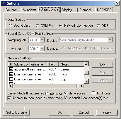
So, go to ATCS Monitor's "Options" tab again,
click it, and then click the "Data Source" tab. Here I
figured we need to enter the Web address one's own ATCS Monitor's
server, in my case:
"rocky-river-ohio-mcp.dyndns.org"
with a port 4802.
to the list of other Web servers (not mine)
that already were listed in the "Data
Source" section of the "my atcs map scanner internet.ini" file.
But this did not work for me.
It
seems
that my network (DSL or
Cable) router-switch
would not let me look
out to the internet and and then back into my my own
LAN. So instead of using "rocky-river-ohio-mcp.dyndns.org"
with
a port 4802, I found out that I could use my LAN address
of the computer running this combined internet plus
scanner instance of ATCS Monitor:
"192.168.1.121"
with a port 4802.
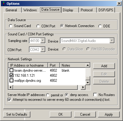
Here
are the screen shots of the important changes made in "my
atcs
map internet.ini" file that became "my atcs map scanner
internet.ini" file.
Screen
shot
1 of Data Source nothing new here
Screen
shot
2 of Data Source nothing new here
Screen
shot
3 of Data Source a new link back to my own
computer on my own LAN: (
"192.168.1.121"
with a port 4802.)
So, when running the "my
atcs
map scanner internet.ini" file (while keeping the "my atcs map
scanner.ini" file running), I was finally able to have the data
feed from my own radio scanner merge with the data from the
Internet.
After saving and re-launching the
"my
atcs map scanner internet.ini" file, and also having the "my atcs
map scanner.ini" file running simultaneously we are in business.
Here
is a screen
shot
of the Cleveland area with combined data from my radio
scanner and from the Internet. My radio
scanner provides data to only the Elmwood control point
part of the map. The other control points that are
in red font are provided with data from the
internet. Here is a sceen
shot
of the data that generates the above map.
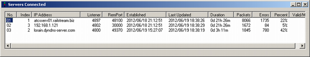
And finally, here is a screen
shot of the "Servers Connected" window. Note
there are three servers listed, the first and third are
feeding my data from the internet, and the middle server
is my very own radio scanner server that is running.
New, July 2015:
How to set
up ATCS Monitor server in a box (less likely to be
stolen from a semi-public location).
Here is my "Automobile
ATCS"
part 1, and
"Automobile
ATCS"
part 2.
Tips
on using
Mobile
Hotspot USB devices to run ATCS Monitor remote servers.